Types of Dampers and their Seismic Performance During an Earthquake
Alireza Heysami1 *
http://dx.doi.org/10.12944/CWE.10.Special-Issue1.119
This paper investigates types of dampers and their performance during earthquake. Also, they have investigated the tall buildings in the world and satisfactory level of damper performance has been studied. And the results show that no only dampers have an acceptable seismic behavior against lateral forces such as wind and earthquake forces. But it has reduced construction limitations of multi-storey building.
Copy the following to cite this article:
Heysami A. Types of Dampers and their Seismic Performance During an Earthquake. Special Issue of Curr World Environ 2015;10(Special Issue May 2015). DOI:http://dx.doi.org/10.12944/CWE.10.Special-Issue1.119
Copy the following to cite this URL:
Heysami A. Types of Dampers and their Seismic Performance During an Earthquake. Special Issue of Curr World Environ 2015;10(Special Issue May 2015). Available from: http://www.cwejournal.org/?p=11096
Download article (pdf) Citation Manager Publish History
Introduction
In seismic structures upgrading, one of the lateral force reduction caused by the earthquake is use of dampers. During an earthquake, high energy is applied to the structure. This energy is applied in two types of kinetic and potential (strain) to structure and it is absorbed or amortized. If structure is free of damping, its vibration will be continuously, but due to the material damping, vibration is reduced. Input energy caused by earthquake to structure is presented in the following equation:
E = Ek + Es + En + Ed .....(1)
In this equation, E is earthquake input energy, Ek is kinetic energy, Es is reversible strain energy in the elastic range and Eh is the amount of wasted energy due to inelastic deformation and Ed is the amount of amortized energy by additional damper. In seismic isolation systems, use of energy dissipation systems, allocated a special place to their selves. Damping increasing is possible by using various methods such as the flow of a soft metal, two metal friction on each other and a piston motion within a slimy substance or viscoelastic behavior in materials such rubber-like substances.
Damping Effect on Structural Response
Damping increasing reduces structural response ( acceleration and displacement) damping effect at low frequency (close to zero) have no effect on spectrum amount and at high frequency, it has low effect on response acceleration. Figures 1 and 2 show the most effect of damping increasing in the frequency of 0.3 to 2.5 seconds.
![Figure 1 – Damping effect on the acceleration response spectrum[2]](http://www.cwejournal.org/wp-content/uploads/2015/05/Vol10_Spe_Type_Ali_Fig1-150x150.jpg) |
Figure 1: Damping effect on the acceleration response spectrum[2] Click here to View figure |
![Figure 2 – damping effect on displacement response spectrum[2]](http://www.cwejournal.org/wp-content/uploads/2015/05/Vol10_Spe_Type_Ali_Fig2-150x150.jpg) |
Figure 2: Damping effect on displacement response spectrum[2] |
Types of Dampers
Dampers are classified based on their performance of friction, metal (flowing), viscous, viscoelastic; shape memory alloys (SMA) and mass dampers. Among the advantages of using dampers we can infer to high energy absorbance, easy to install and replace them as well as coordination to other structure members.(journal,2006).
Friction Dampers
In this type of damper, seismic energy is spent in overcoming friction in the contact surfaces. Among other features of these dampers can be classified as avoiding fatigue in served loads(due to the non-active dampers under load) and their performance independent to loading velocity and ambient temperature. These dampers are installed in parallel to bracing (journal,2006).
![Figure 3 – the effect of using friction dampers on structure capacity curve.[3]](http://www.cwejournal.org/wp-content/uploads/2015/05/Vol10_Spe_Type_Ali_Fig3-150x150.jpg) |
|
In figure 4, rotational friction dampers are shown. Because of very simple behavior and easy to install and make, this type of damper is converted to one the most common types of friction dampers.( Warn,2004)
![Figure 4 – using rotational friction dampers in retrofitting[5]](http://www.cwejournal.org/wp-content/uploads/2015/05/Vol10_Spe_Type_Ali_Fig4-150x150.jpg) |
|
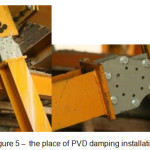
PVD Damper
It is another type of friction damper and due to ease to installation, is one of the most widely used damper in structures( Warn,2004). PVD damper can be used to create necessary damping for flexible structures, such as bending steel frame or to provide effective damping to relative stiffness of structures(Naeim,1995). PVD damper is designed to installation where displacement can generate necessary damping such as installation of metal skeleton brace or concrete moment frame.
 |
|
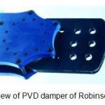
The first building which was designed by Iranian designer and by using PVD damper of Robinson company and it was a building with private owner in and with 164/5 squares meters area and it will be built in 6 floors. This building is located in Rey. The floor is about 112 square meters. And its main skeleton is a type of steel and screws and nuts type. In this building, the retrofitting new technology is used for earthquake called seismic dampers system. The numbers of PVD dampers are 12 damper of 100 KN. Another high-rise building was designed in northern Tehran with 19 dampers of 350, 600, 850 KN PVD of Robinson company by another designer which are in ordering stage.
 |
|
In equipment and dependent dampers on the lead such as lead rubber bearings and lead dampers which are used as the best and most successful protective equipment for different structures against earthquake. And they are invented in New Zealand country by Rabinson company at DSIR physics and engineering laboratory. And they have been used as the best dampers extensively in last 30 years. PVD damper are designed based of lead plastic deformation such as lead rubber bearing. For rubber lead bearing, the created damping force by lead is less than elastic force related to rubber, while for PVD, damping force of lead is much greater than rubber elastic force. Now, PVd is used as an effective damper on many bridges, towers, buildings. The advantages of PVD damper include(Hwang et al.,1994):
- PVD damper acts effectively on low displacements. For example, one 1MN PVd damper can acts effectively for 0.5 mm to 5 mm displacement.
- PVD damper requires no maintenance and does not have any lubrication or winder components.
- PVD damper behavior is like the behavior of a metal damper.
There are damper equipment in which lead is used and they are installed in thousand different structure around the world. But protecting high-raise structures with different volition with long periods such as tall building is impossible due to conventional systems or it is not economic[8]. Rabinson company invented PVD damper as a solution. And it can reduce short and long established structure. This damper can be used to damping small fluctuations and wind in tall structures. Also, we can reduce replacement caused by earthquake. PVD is a damper can create a significant amount of hysteretic damping in small replacements small to +/- 50 micrometer. By distributing PVD damper in the structure, we can increase the size structure damping. This damper is suitable to protect structure volatility with a wide number of different periods. And finally, it creates high damping for structure. Practical design range for a PVD sample with a capacity of 200 KN based on obtained results include that it is in the range of +-50 micrometer to +-10mm. greater displacement need a larger type but its sensitivity will decrease.
Pall Friction Damper
Another type of friction damper is Pall friction damper. (figure 1-2-1-2). This damper includes a bracing and some steel plate with friction screws. And they should be installed in the middle of bracing. Steel sheets are connected to each other by high strength bolts and they have a slip by a certain force, to each other.
![Figure 7 – using Pall friction dampers[12].](http://www.cwejournal.org/wp-content/uploads/2015/05/Vol10_Spe_Type_Ali_Fig7-150x150.jpg) |
|
![Figure 8 – using Pall friction damper in retrofit[12]](http://www.cwejournal.org/wp-content/uploads/2015/05/Vol10_Spe_Type_Ali_Fig8-150x150.jpg) |
|
Metallic Dampers (submission)
In this damper, transferred energy to the structure is spent to submission and non-linear behavior in used element in damper. In these dampers, metal inelastic deformation is used such as for formability metals such as steel and lead for energy dissipation. In all conventional structures, energy dissipation is based on deformation of steel members after the submission.
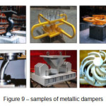 |
Figure 9: Samples of metallic dampers Click here to View figure |
In braces, using submission metallic dampers is more common. These dampers are often created by some parallel steel plates. And in combination with a bracing system, they undertake the role of absorption and energy dissipation. This part of bracing can acts as a fuse in structure. And by focusing on nonlinear behavior prevent non-linear behavior and damage in other major and minor structure parts.
![Figure 10 – effect of using submission metallic dampers on structural capacity curve[13]](http://www.cwejournal.org/wp-content/uploads/2015/05/Vol10_Spe_Type_Ali_Fig10-150x150.jpg) |
|
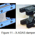
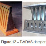
X-shaped metal dampers have a significant performance. Massive submission on steel volume, providing Hysteretic damping and extraordinary energy dissipation are unique features of this type of damper. These dampers have a high lateral stiffness, in addition to providing damping. So, they were entitled as Added Damping And Stiffness (ADAS).
 |
|
 |
|
These dampers are installed between head chevron tracings and floor beams. And by good connections, these dampers can be installed in concrete frames.
Lead Injection Damper (LED)
This damper is made of a two-chamber cylinder, piston and lead inside piston. And by piston moving during earthquake, lead moves from larger chamber to smaller chamber. And with plastic deformation, the kinetic energy is wasted as heat. In figure 1-1-2-3, the longitudinal section of lead damper injection is shown(Saiidi et al.,1999).
![Figure 13 – longitudinal section of lead damper[12]](http://www.cwejournal.org/wp-content/uploads/2015/05/Vol10_Spe_Type_Ali_Fig13-150x150.jpg) |
Figure 13: Longitudinal section of lead damper[12] Click here to View figure |
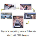
Shape Memory Alloy (SMA)[14]
Shape Memory alloy (SMA) are created from metals which have the following properties:
- their flexibility is very similar to the flexibility of the rubber piece.
- after applying many deformation, they can back to their original state, by heating.
The alloy of nickel and titanium has good resistance to corrosion, in addition to have these properties.
 |
|
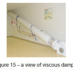
Viscous Dampers
In this damper, by using viscous fluid inside a cylinder, energy is dissipated. Due to ease of installation, adaptability and coordination with other members also diversity in their sizes, viscous dampers have many applications in designing and retrofitting.
 |
|
![Figure 16 – details of viscous damper system type[14]](http://www.cwejournal.org/wp-content/uploads/2015/05/Vol10_Spe_Type_Ali_Fig16-150x150.jpg) |
|
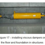
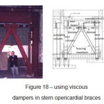
This type of dampers are connected to the structure in three ways:
- damper installation in the floor or foundation ( in the method of seismic isolation)
- connecting dampers in stern pericardial braces
- damper installation in diagonal braces.
 |
|
In connecting dampers on the floor or foundation of structures, we can use a combination of dampers with isolators.
 |
|
Mass Damper
Mass is placed on a fulcrum which acts as a roller. And it allows to mass with move as a transfer-lateral movement to the floor. Springs and dampers are placed between mass and anchor members to the floor and frame and they are placed relative in “opposite phase” and sometimes are adjacent vertical. And these anchor members transmits structural lateral force. Bidirectional transfer dampers are made as a spring-damper in two vertical directions. And they provide controlling the structure movement in two vertical structures.Seismic isolator is used to isolate the structures of strong ground motions during an earthquake. Unlike building which its isolation is often done on the foundation, this separation is applied between topside of structure and below side of that in bridges. This is due to a high inertia force of topside (including deck weight) also it will be easy to use. The main objective in seismic isolation is to reduce base frequency of structure vibration and reaching it to a lower value than frequencies which have main earthquake energy. In other word, seismic isolation increases structure vibration period and bridge and distances it from periods containing earthquake main energies. So, the input energy to base caused by earthquake is reduced with seismic isolation. Another advantage of seismic isolation is to provide a tool to waste energy. So, inputted energy to structure get wasted in small points and by a controlled manner. Thus, destruction and damaging in particular and few concentrated points will be exist and it will be possible to replace these parts after the earthquake. In general, seismic isolation design lead to reduce the structures responses reduction which are in earthquake conditions (Ryan et al.,2004).
- increasing main period
- increasing relative damping (energy dissipation)
Isolation objectives in a bridge is quite different with a building. In a building, due to reducing the energy forces applied to topside and to reduce stress, isolators are installed in structural elements. But in a separate bridge, seismic isolator is installed to keep the elements under isolators ( backpacks and base) to reduce the transmitted energy force and change topside places (deck) to below side structures ( backpacks and base).
![Figure 19 – mass damper model in the building[15]](http://www.cwejournal.org/wp-content/uploads/2015/05/Vol10_Spe_Type_Ali_Fig19-150x150.jpg) |
|
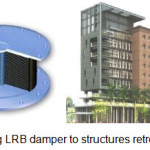
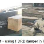
Lead Rubber Damper LRM and Rubber Damper HDRB
We use isolator in bridge design in order to achieve maximum energy absorption (relative to the period of the isolated structures). So we should use isolators which have a high damping. And from this perspective, LRB seismic isolator has an intrinsic property 30% (independent of vibration frequency, temperature and environmental conditions).
 |
|
 |
|
For bridges designing because of the movement limitation, the effect of increasing alternative period is low in the most projects, but the damping effect in bridges is higher than construction projects.
Since seismic isolator prior to stability testing is places long-term loads and thermal conditions, also the philosophy of that resistance which is much greater that exploitation forces. And isolator buckling stability is controlled against these forces. So the design principles are gravity and lateral earthquake loads. As a result, damping increasing is the main factor to select LRB with 30% damping against to HDRB with at most 10% damping for bridges. In 1982, the English company of Malaysian manufactures research institute have developed a nature rubber compound. And intrinsic damping is so much and there was no need to use additional damper to approximately 10%. The damping of this rubber compound is obtained by adding ultrafine carbon blocks, oils or resins and other special fillers. Damping can reach to 10 to 20 percent in shear strain equivalent to 100 percent. And its lower limit 10 percent is related to damping with low stiffness( hardness equivalent to 50 to 55 with hardness determinism). With a shear model about 0.34 MPa (PSI 50), the upper unit of that relates to systems with high stiffness ( stiffness about 70-75) and upper shear model is about 1.4 Mpa (PSI 200). The vulcanized methods, pasting and construction of isolators are nor changed and is the same as before. The resulting material in shear strain is less than 20 non-linear and its feature is higher stiffness and damping ( in more strain). And it can minimize response time under load and extremely low seismic loading. In the field of shear strain between 20 to 10 percent, the percent of shear module amount is low and constant. In high strain, due to the strain crystallization process in rubber along with increasing energy dissipation (capacity), and this module value is increased. These stiffness and damping increasing can be used at high strains to system production. And they are hard for small loads (input) and for inputs in design range are linear and flexible. And under unanticipated input levels which are more than design values, they limit displacement. Damping is not vascular isolators nor waste, but it is something between this two things. In a highly viscous linear element, the depreciate energy is proportional to the fourth power of displacement and it is changed in a waste system (Hysterical) as a linear displacement.Experiments carried out on a number of different rubber isolators are on EERC. And depreciate energy is proportional to displacement with 1.5 power. This feature can use to modeling session response which include linear viscous elements and elements of rubber-plastic (elastic-inelastic) elements. Another inherent advantages of HDRB systems is that they cause some reduction in environment vibration. These isolators are created as a filter for high frequency vertical vibrations in traffics with lateral underground railway lines, this effect is shown in a shaking table tests in EERC in 1985. Lead-rubber seismic isolators are like to rubber sessions with low damping but they have a lead core. And a hole is located in their center. Lead has a high initial shear stiffness and low shear flow and they have full elasto plastic behavior and non-fatigue appropriate characteristics in plastic cycle. These lead characteristics lead to this issue the lead-rubber seismic isolators have a high horizontal stiffness against service loads and high energy waste against string seismic loads. And these are on high energy waste and service loads against string seismic loads. Lead cores deformed in shear stress about 10 MPa and this is a physical deformation and cause two linearity response in session. This isolators plates one of the rubber and steel. Steel pages play a role in bearing vertical loads of service and horizontal loads. In vertical service loads, steel plates prevent rubber lateral expansion. And session vertical stiffness can increase significantly, while they have no effect on session horizontal stiffness which are controlled by low shear modulus elastomer. In seismic horizontal loads, steel plates deformed lead core in cutting. The effect of LBR seismic effect on leak length and width displacement and applied forces to basis and energy absorbance and increasing the isolator period is dependent to displacement. Due to the displacing limitation in the longitudinal direction of deck (lack of collision of deck to backpacks during an earthquake), the amount of optimizing energy absorbance by LRB against the performance of its period increasing is the main issue in designing LRB elements designing. Since that the effective part to the performance of LRB energy absorbance is its lead core and it effective part to increasing period is time of structure to height ratio to LRB width. (Ryan et al.,2004)
Comparing LRB with HDRB(Ryan et al.,2004) :
- LRB will have damping to 30% but HDRB will have damping between 10% to 15%.
- to start LRB movement, due to this fact that first lead should flows from stiffness to flowing phase, it has a greater time delay than HDRB.
- HDRB price is less than LRB price.
- HDRB has a lower resistant movement against weaker earthquakes and wind than LRB due to the initial lead stiffness.
- HDRB have more sensitivity to environmental vibrations than LRB.
- LRB performance relative to earthquake is better than HDRB.
To accept the full advantages of LRB by using LRB and HDRB in bridges of New Zealand, America and Japan, this work was done. That in New Zealand only in 35 bridges, LRB was used and HDRB is not used. And this America in 90 bridges, LRB is used and only in 2 bridges, HDRB is used. And in Japan in 27 bridges, LRB and in 7 bridges, HDRB is used. But it should be noted that in these 3 countries, in buildings, the distance between using LRB relative to HDRB is far more than HDRB. And they use HDRB only for tanks.
LRB and HDRB Damper Resistance Against Disruption
Disruption forces may be created from earthquake vertical element or couple obtained by earthquake horizontal force in corners columns, so known manufacture companies of seismic isolator to solve the problem of disruption in isolator, laminated rubber to end steel plate within isolator. They connect base Plate by bolts to the end plate within isolator. And during installation seismic isolators, and they connect Cover plate of column by inhibitory Bolt to sub Structure of isolator and Super Structures of isolators. And during occurring disruption in columns, isolator acts as integrity factor of sub structure and super structure. To dealing with higher uplift, when LRB or HDRB is applied, tension system is used which was invented by famous company Holmez from New Zealand.
 |
|
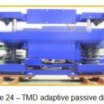
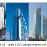
Regulatory Mass Damper TMD [14]
TMD is a passive damper which was created in 1970s in America and 1990s in Japan only to dealing with wind and created seismic in structures such as created stomp and oscillation and they were used by peoples that they can respond for small earthquakes. And then, in Japan, Active +TMD systems such as SATMD, HMD AMD, APTMD were considered for strong earthquakes.
![Figure 23 – system basis and locations of TMA[14]](http://www.cwejournal.org/wp-content/uploads/2015/05/Vol10_Spe_Type_Ali_Fig23-150x150.jpg) |
Figure 23: System basis and locations of TMA[14] Click here to View figure |
Passive Seismic Controlling System
People when are in moving train or they are stand in a bus, try to maintain their balance by their foot and by relying on spine and abdominal muscles. In the same way or by providing same features for structure, structure can damped vibrations at the time of earthquake. This system includes movable mass which is set to the spring and it is added to damping components. And by creating frequency dependent to hysteresis, it increases damping in first structure. And by connecting a TMD to structure, structure seismic energy is transferred to TMD and its energy depreciates in TMD damper(Jangid,2004). As a result, it is used to reduce the structure dynamic response. Passive control system does not need t0 a power supply to provide external power. And reaction of passive control components in response is dependent to structure movement during earthquake. In structure passive controlled system, energy which includes passive components can not increase its stability by passive control components(Saiidi,1999). Passive components methods are strongly dependent to exact setting and must be specifically design for each structure, because they are not able to adapt structural changes and usable parameters changes. And for all conditions, required loads are not optimized. As a result, passive systems can be effective only for violation cases that are designed or adapted, accurately(Jangid,2004).
 |
|
Active Seismic Control Systems (Active)
Compared with passive control system, active control system structural response is controlled, effectively by 2 factors,
- By a special amount of output power or required energy.
- The process of decision-making based on measured real-time and involved data.
In this respect, active control includes a widespread technology. In terms of engineering control, active control system is composed of 4 connected components, these includes:
Structure, sensor, computer control and controller and actuators, each of them works as lateral system. And they are integrated that an output of a systems is an input of another system is a feedback control system. So, priority of an active systems is in widespread use due forces controlling and they are created by real stimulating and structural behavior. In active system, when the output excitation is considered as an output. And it is called open-loop system. When the structure response is used as an input, the system us called closed-loop. When both excitation and response are used, system is called open-close control system (Hwang et al,2007).
Hybrid and Semi-Active System
The term of hybrid control systems is used for a hybrid using of active and passive control systems. Semi-active systems are extracted from active control systems. In this cases, the required output energy is lower than active control system. And it is only the producer of electric pulse to provide control system. Semi active control components dose not add mechanical additional energy to structure system ( which includes structural and stimulus control), so the stability of input and output connections are guaranteed. Semi-active control components often can be seen as passive control components. Particularly, more resistant or depreciate forces are produced by internal mechanism based on feedback output sensor. So the combination ability of the best active and passive systems or against less reduction of desired components and due to low power, have high control ability. Semi-active systems are an attractive alternative for active and hybrid systems.
 |
|
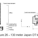
130 Meters DT Tower in the Year of 2002 in Japan (Ryan et al.,2004)
This building has 27 floors and in third floor, it became a seismic isolator. Seismic isolation is so effective for preventing earthquake excitation. But they have the opposite effect for the ling natural period against wind. So seismic isolators were designed and during strong wind, they are fixed mechanically. On the other hand, the main structure is metallic, vibration during strong wind is highly enough to disrupt in upper classes, as a result 2 TMD with 2 ice storage tank each of them of 270 tons were used to improve structural response against strong wind which are interruptions causes.
 |
|
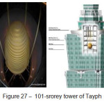
101 Floor Tapyh Tower(Ryan et al.,2004)
Inside this tower, Tapyh World Financial Center in Taiwan is the largest and heaviest regulated damper (TMD) which is installed globally. And they act as a big pendulum, a big steel core that is moved slowly in front and rear of each movement of building. This is an engineering feat and is able to limit the vibration of a tall building above 500 meter. A steel core with 5.5 m diameter and 728 tons weight are suspended with 8 cables from the top floors of the tower. And they are visible between floors 88 and 92. And it is one of the tallest structures in the world which are located about 200 meters from main fault line and wind and earthquake are serious problems for this structure. In fact, tourists could even take photos from this TMD during sishan earthquake. In this 101-story towers, this steel core able to bear 1.5 meter movement in each direction. And they reduce the vibration range about 30 to 40%.
 |
|
References
- Robert. D. Hanson, TSU T. Soong; “Seismic design with supplemental energy dissipation devices” published by Earthquake Engineering Research Institute,145-156(2003)
- Trevor E Kelly Holmes Consulting Group, Damper Design Guidelines, (2001)
- Journal of the seismic rehabilitation of existing buildings 360-2006 instructions "Department of Engineering Management and Planning”,(2006)
- Warn, G. P. and Whittaker, A. S. "Performance estimates in seismically isolated bridges", Engineering Structures, Vol.26, pp. 1261-1278(2004).
- Naeim, F. & Kelly, J. M, John Wiley and sons. "Design of seismic isolated structures from theory to practice",(1999).
- American Association of SÙtate Highway Officials "Guide Specifications for Seismic Isolation Design", Washington, D.C., American Association of State Highway Officials , (1999).
- Hwang, J.S. and Sheng, L.H. "Equivalent elastic seismic analysis of base-isolated bridges with lead-rubber bearings", Engineering Structures, Vol.16, No.3, pp. 201-209(1994).
- Hwang, J.S. and Chiou, J.M. "Equivalent linear model of lead-rubber seismic isolation bearings", Engineering Structures, Vol. 18, No.7, pp. 528-536(1996).
- Hwang, J.S. , Chiou, J.M., Sheng, L.H. and Gates, J.H. "A refined model for base isolated bridges with bi-linear hysteretic bearings", Earthquake Spectra, Vol.12, No.2, pp. 245-273(1996).
- Ghobarah, A. and Ali, H.M. "Seismic performance of highway bridges", Engineering Structures, Vol.10, No.3, pp. 157-166(1988).
- Pagnini, L.C. and Solari, G. "Stochastic analysis of the linear equivalent response of bridge piers with aseismic devices", Earthquake Engineering and Structural Dynamics, Vol.28, No.5, pp. 543-560(1999).
- Saiidi, M., Maragakis, E. and Griffin, G. "Effect of base isolation on seismic response of multi-column bridges", Structural Engineering Mechanics, Vol.8, No.4, pp. 411-419(1999).
- Chaudhary, M.T.A., Abe, M. , Fujino, Y. and Yoshida, J. "Performance evaluation of baseisolated Yama-age Bridge with high damping rubber bearings using recorded seismic data", Engineering Structures, Vol.23, No.8, pp. 902-910(2001).
- Jangid, R.S. "Seismic response of isolated bridges", Bridge Engineering, Vol.9, No.2, pp. 156- 166(2004).
- Ryan, K. L. and Chopra, A. K. "Estimation of seismic demands on isolators based on nonlinear analysis", Structural Engineering, Vol.130, No.3, pp. 392-402(2004).