Experimental Investigation and Techno Economic Analysis of open Core Gasifier By Using shredded Cotton Stalk as feedstock
U. D. Dobariya 1 * and P. N. Sarsavadiya 1
1
Department of Renewable Energy and Rural Engineering,
CAET JAU,
Junagadh,
362001
India
http://dx.doi.org/10.12944/CWE.11.1.38
Investigation on gasification of shredded cotton stalk was carried out by developing an open core throat less downdraft gasifier reactor (capacity: 70 MJh-1).Performance of the gasifier was carried out at six different gas flow rate (12, 14, 16, 18, 20 and 22 m3/h)levels.The gasifier performed best at 18 m3h-1gas flow rate with equivalence ratio,gasification efficiency, specific gasification rate,specific gas production rate and fuel consumption rate of 0.35, 71.05 %, 192.51 kgh-1m-2,481.28m3h-1m-2and 7.2 kgh-1respectively. The economic analysis was carried out by considering shredded cotton stalk as feed stalk and compared with briquette. The benefit cost ratio of the gasifier systemwas increased from 1.45 to 2.18 (50.34%) and payback period decreased from 5y9m to 3y 5m (40.39 %) considering shredded cotton stalk as feed stock and compared with briquette for (gas flow rate: 18 m3h-1, daily operation: 20 h per day) 270 days of operation per year.
Copy the following to cite this article:
Dobariya U. D, Sarsavadiya P. N. Experimental Investigation and Techno Economic Analysis of open Core Gasifier By Using shredded Cotton Stalk as feedstock. Curr World Environ 2016;11(1) DOI:http://dx.doi.org/10.12944/CWE.11.1.38
Copy the following to cite this URL:
Dobariya U. D, Sarsavadiya P. N. Experimental Investigation and Techno Economic Analysis of open Core Gasifier By Using shredded Cotton Stalk as feedstock. Curr World Environ 2016;11(1). Available from: http://www.cwejournal.org/?p=13689
Download article (pdf) Citation Manager Publish History
Introduction
India has the largest area in the world (9 mn ha) under cotton cultivation and is the largest producer of cotton (2.7 mn MT, 0.3 MTha-1). Cotton is produced in 9 states in India viz. Haryana, Punjab, Rajasthan,Gujarat, Maharashtra, M.P.,Andhra Pradesh, Karnataka and Tamil Nadu. Gujarat state is the largest cotton producer in India and accounts for about 714000 MT of India’s total production with only 18 % (1.6 mn ha) of India’s total area under cotton cultivation with an average productivity of 0.45 MT. The major agricultural wastes generated in Gujarat are cotton stalk (50 lakh MT), rice husks (3 lakh MT), maize wastes (20 lakh MT), bagasse (40 lakh MT) and groundnut shells (8 lakh MT).1 Cotton stalk has about same heating value (17 MJkg-1 on dry basis) as wood and half that of a good quality coal. It has found much use as an energy resource due to good combustion characteristics.
Among the various techniques available for converting solid biomass into useful form of energy, gasification is receiving prime importance for research, development and applications, particularly in developing countries. Almost all types of agro-industrial and agricultural residues can be easily used as fuel in gasifiers due to their high volatility, high char reactivity and low sulphur content. Gasification is a thermo chemical process, which converts the solid biomass, in oxygen deficient environment, into combustible producer gas. The calorific value of producer gas varies from 4 to 6 MJNm-3 for gasifier using air. The major combustible components of producer gas are carbon monoxide, hydrogen, methane, and non-combustible hydrocarbons.
Gasifiers can be mainly classified as downdraft,updraft, cross draft, and fluidized bed.Down draft gasifiers are characterized by co-current flow of air or gas and the fuel. In down draft (with or without throat) gasifier, tar and other products of pyrolysis are passed through the high temperature oxidation zone of the reactor where they are subsequently burnt or cracked. Thus, the producer gas from a down draft gasifier contains very less tar (less than 1 %,.2) and therefore, downdraft gasifier are popular for engine applications as also used for thermal application. However, these gasifiers are highly fuel specific.3,4,5,6 Down draft gasifier with throat produce best quality producer gas, but it is not suitable for gasification of agro-residues like cotton stalks. For this type of biomass, throatless gasifier is more suitable. The reaction zones sequence in this gasifier is also similar to that of the down draft gasifier with throat. The open core throat less downdraft biomass gasifier is suitable for small sized biomass having high ash content up to 20 %.7,8,9 Cotton stalks and other agricultural crop residues are available in plenty and are very potential as sourceof energy. These residues are sometimes burnt in the field itself in this region which creates adverse condition to soil health. Utilization of these agricultural residues in open core gasifier may not only solve the problem but convert it in to useful energy. However,before using whole cotton stalk in the gasifier, it is to be converted into the shredded form of cotton stalk,to be used as feed stock.
Keeping this background in mind, the present study was undertaken on the experimental evaluation of the gasification of shredded cotton stalk by developing an open core throat-less downdraft biomass gasifier. Simultaneously,the economic analysis was also carried out by considering the shredded cotton stalk as feed stock and compared with briquette.
Material and Methods
The shredded cotton stalk was used as feed stock in the gasifier during the present study. As the whole cotton stalk biomass cannot be used directly in the gasifier reactor, it was converted into shredded material with the help of cotton stalk shredder.
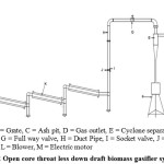
Open core throat less downdraft biomass gasifier system
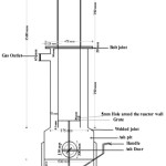
The gasifier system mainly consists of a gasifier reactor, cyclone separator, gas duct pipe, cooling unit and thermal unit.The gasifier reactor was designed for 70 MJh-1(19.44 kW) thermal capacity by considering shredded cotton stalk as feed stock.Various assumptions considered for the design and development of open core throat less down draft gasifier reactor is given in Table 1.Design dimensions of open core throat less down draft gasifier are obtained as per the method explained by10; and.11 As per the design, reactor was developed with the dimensions given in Table 2. The detail of the reactor is shown in Fig.1.The annular space of the lower section of the reactor was provided between the two cylinders for gas flow and to act as insulation for maintaining the temperature inside the reactor.The inner cylinder of the upper section was insulated and provided with GI sheet cladding to reduce heat losses. A flange joint with graphite gasket was provided to joint upper and lower sections of reactor.The open top end was provided with air tight lid for stopping the air into the reactor while closing the operation of reactor.During operation, top of the gasifier remains open and air enters the reactor from the top.
Table 1: Assumptions for the design of open core down draft gasifier reactor
|
Sr.No. |
Assumption parameters |
Value |
|
1 |
Thermal capacity, P (MJh-1) |
70(19.44 kW) |
|
1 |
Lower heating value of biomass, Hw (kJkg-1) |
16.01 x 10³ |
|
2 |
Gasification efficiency,ηg (%) |
70 |
|
3 |
Burner efficiency,ηb(%) |
90 |
|
4 |
Overall system efficiency,η(%) |
63 |
|
5 |
Lower calorific value of producer gas, Hg (kJm-3) |
4.2 x 10³ |
|
6 |
Density of biomass, Sp(kgm-3) |
157.30 |
|
7 |
Time of operation, t ( h) |
1.25 |
|
8 |
Specific gasification rate, SGR (kgh-1m-2) |
185 |
The air as passes through the combustion zone is converted to producer gas. The gas then passes through the grate and flow upward through annular space. A grate was kept inside the reactor at 65 mm above the bottom of the inner cylinder to hold the biomass as well as to allow the producer gas to pass through it. The grate was made from 8 mm thick SS rod with 4 mmgap between two rods. Manual shaking mechanism was provided to avoid bridging and channeling. The ash pit is closed from the bottom. The air tight ash door is provided on the side of ash pit for removing the ash. The reactor was fitted on the MS standas shown in Fig.1.A 65 mm diameter gas outlet was provided to the reactor. This gas outlet was suitably connected tothe inlet of cyclone separator.Gas outlet of the cyclone separator is provided at the top of the cyclone separator as shown in Fig.2. The cyclone separator is developed on the basis of the method described by.12
Outlet of the cyclone separator is connected to the burner with the help of gas duct pipe (65 mm diameter)for carrying the gas via cooling unit. A wheel valve, GI bands, calibrated orifice plate(for measuring the gas flow rate)etc was used for connecting the gas duct pipe.The whole cooling unit is divided into three separate water jacketed concentric pipe sections and connected with each other. Water is continuously supplied and circulated in the annular space between the inner and outer pipe at the inlet end and removed through the outlet end. A centrifugal blower is used to draw the producer gas from the system. Burner was connected with outlet of blower by GI pipe (40 mm diameter). The gate valve was provided between outlet end of the blower and burner for regulating the producer gas to the burner. An another pipe (15 mm diameter)with small blower (50 cfm, 0.25 hp, 1Φ) was connected to the 40 mm diameter pipe for supplying the producer gas to the Junker’s gas calorimeter for determining the calorific value of producer gas.
Performance of the Gasifier
Performance of the gasifier was evaluated at six different gas flow rates of 12, 14, 16, 18, 20 and 22 m3h-1by using shredded cotton stalk biomass as feed stock. Performance of the gasifier was evaluated in terms of feed stock consumption rate(FCR), specific gasification rate (SGR), specific gas production rate (SGPR), equivalence ratio (ER), calorific value of gas (CVg), gasification efficiency(η), output energy and amount of residual char.
Table 2: Specifications of the designed and developed gasifier
|
No. |
Components |
Specifications |
|
1. 2. |
Fuel consumption, Quantity of gas production, |
6.93 kgh-1 18.50 m3 h-1 |
|
3. |
Reactor |
Cylindrical |
|
Type |
Open core throat less down draft |
|
|
Volume, area, diameter and |
0.0550m3, 0.0374m2, 0.0218m (= 0.0225 m) |
|
|
height |
and1.4765m (= 1.5 m) |
|
|
Material |
MS sheet, 4mm thick |
|
|
Upper section |
750 mm high, ceramic wool insulated (5mm) covered by GI sheet (0.5 mm) cladding |
|
|
Lower section |
750 mm high, jacketed, 75 mm annular space for gas flow, both sections jointed by flange |
|
|
Grate |
Circular, 222 mm diameter made from 8 mm diameter SS rod |
|
|
Ash pit |
500 mm diameter and 300 mm height |
|
|
Ash pit door and air tight lid |
150 mm diameter; and 200 mm diameter lid (made from 15 mm thick MS plate) |
|
|
Gas outlet |
65 mm diameter |
|
|
Stand |
200 mm high x 740 mm wide made from 50 x 50 x 5 mm MS angle |
|
|
4. |
Cyclone separator |
Made from 2 mm thick MS sheet |
|
Cylindrical section |
125 mm diameter and 250 mm height |
|
|
Conical section |
325 mm height, diameter of lower end reduced to 30 mm and connected to closed bowl |
|
|
Gas inlet section |
Rectangular, 25 mm wide x 50 mm height |
|
|
Gas outlet section |
Circular, 65 mm diameter |
|
|
5. |
Gas outlet pipe duct |
Made from 65 mm diameter GI pipe coupled by flange, band, wheel valve and orifice plate |
|
6. |
Cooling unit |
Water jacketed (3 nos.) concentric pipe sections (31.5 mm annular gap) for water circulation connected with each other having water inlet, outlet and drain plug. |
|
Inner (gas flow) pipe |
890 mm length x 65 mm diameter |
|
|
Outer (water flow) pipe |
812 mm length x 128 mm diameter |
|
|
7. |
Centrifugal blower |
Capacity: 200 cfm, operated by 1Φ, 0.5 hp, 2800 rpm electric motor |
|
8. |
Thermal unit (Burner) |
Concentric cylinder type (25 mm annular gap) |
|
Inner (gas flow) cylinder |
140 mm length x 205 mm diameter |
|
|
Outer (air flow) cylinder |
215 mm length x 255 mm diameter |
 |
|
 |
|
Amount of shredded cotton stalk consumption was measured by weighing the cotton stalk before feeding into the gasifier for the total time period of each test run. The effective operational time of the gasifier was used to calculate the rate of cotton stalk biomass consumption in kg h-1. Specific gasification rate indicates the amount of fuel fed to gasifier per unit cross sectional area of the reactor in one hour. Specific gas production rate is the amount of gas produced per unit cross sectional area of gasifier reactor.
Equivalent ratio is the ratio of actual air used in a run to stoichiometric air requirement for the run. The actual air consumption was measured from the top of the gasifier by using vane type anemometer. The stoichiometric air was calculated by using the elemental composition of the cotton stalk.13 Calorific value of the producer gas was measured on line with the help of Junker’s gas calorimeter. Gasification efficiency is the percentage energy of biomass converted into producer gas. Output energy is the product of gas flow rate and its calorific value. Amount of residual char was also measured after each test run.
Economic Analysis
Economic analysis of the developed gasifier system was carried out for shredded cotton stalk and briquette as feed stock for thermal application by considering the assumptions given in Table 3.The analysis was carried out for 270, 300, 330 days of operation per year, at different operating hours per day i.e. 12, 14, 16, 18 and 20 h; and 18m3 h-1gas flow rate at which the reactor showed best performance. Economic analysis was carried out by employing economic indicators of net present worth, benefit-cost ratio and payback period as per the method used by.10 The difference between the present value of all future returns and the present money required to make an investment is the net present worth (NPW)for the investment. The present value of the future returns can be calculated through the use of discounting. The interest rate was assumed as the discount rate for discounting purpose.Benefit cost ratio (BCR) is the ratio obtained when the present worth of the benefit stream is divided by the present worth of the cost stream.
Table 3: Assumptions for economic analysis of the gasifier system
|
No. |
Assumption parameters |
Value |
|
1 |
Life of the biomass gasifier system, years. |
10 |
|
2 |
Salvage value at 10% of initial investment. |
|
|
3 |
Interest at 10% of initial investment. |
|
|
4 |
Depreciation at 20% of initial investment spread over, years. |
10 |
|
5 |
Repair and maintenance cost at 20% of initial investment spread over, years. |
10 |
|
6 |
Discount rate, %. |
10 |
|
7 |
Electricity cost Rs. kW-1h-1. |
06 |
|
8 |
Life of the biomass gasifier system, years. |
10 |
The formal selection criterion for the benefit cost ratio for measure of project worth is to accept projects for a benefit cost ratio of one or greater. The payback period is the length of time from the beginning of the project until the net value of the incremental production stream reaches the total amount of the capital investment. It shows the length of time between cumulative net cash outflow recovered in the form of yearly net cash inflow.
Results and Discussion
Results on the physical and thermal properties of cotton stalk biomass, development of open core throat less down draft biomass gasifier, performance of open core throat less down draft biomass gasifier, and economic analysis of the gasification have been analyzed and discussed in the following section
Performance of open core throat less downdraft biomass gasifier
Performance of the gasifier was carried out at six different levels of gas flow rate (12, 14, 16, 18,20 and 22 m3 h-1). Performance parameters likefuel consumption rate (FCR), specific gasification rate (SGR), specific gas production rate (SGPR), equivalence ratio (ER), calorific value of producer gas, cold gasification efficiency, output energy and residual char production were determined at all the six levels of gas flow rates in the present study.
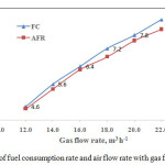
The variation of fuel consumption rate and air flow rate at different levels of gas flow rate are shown in Fig.3.It can be seen from the figure that as the gas flow rate is increased; the fuel consumption and air flow rateis also increased.It is obvious that, as the gas flow rate is increased, the air requirement is increased for the increase in gasification reaction rate with increase in fuel consumption rate.The fuel consumption rate and air flow rate were found as 4.6, 5.6, 6.4, 7.2, 7.8 and 8.5 kgh-1; and 6.99, 10.49, 13.99, 16.33, 19.23 and 21.25 m3 h-1 at different levels of gas flow rate of 12, 14, 16, 18, 20, 22 m3 h-1 respectively. The results of the present study were in accordance with the results presented by.13 They found that subabool wood consumption rate was increased from 7.5 to 12.5 kgh-1 with increase in gas flow rate from 11.14 to 20.34 Nm3h-1.14 also examined the increased trend for cashew nut shell consumption rate from 23 to 47 kgh-1 with increase in gas flow rate from 61 to 130 m3h-1.
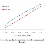
The variation of specific gasification rate at different levels of gas flow rate is shown in Fig.4. It can be seen from the figure that the value of specific gasification rate is increased with increase in gas flow rate. The value of specific gasification rates were found as 122.99, 149.73, 171.12, 192.51, 208.56 and 227.27 kg h-1m-2at different gas flow rates of 12, 14, 16, 18, 20 and 22 m3h-1 respectively. It is also obvious that the behavior is similar to that of the behavior of fuel consumption with gas flow rate as seen in Fig.3.
 |
|
 |
|
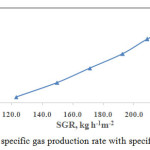
The effect of gas flow rate on specific gas production rate is shown also shown in Fig.4. It can be seen from the Fig.4 that the value of specific gas production rate is also increased with increase in gas flow rate.The values of specific gas production rate was found as 320.86, 374.33, 427.81, 481.28, 534.76 and 588.24 m3 h-1m-2 at different levels of gas flow rates of 12, 14, 16, 18, 20 and 22 m3 h-1 respectively. The results of specific gas production rate at different gas flow rates in the present study was in accordance with the results obtained by.15 and reported that the SGPR was increased from 174.8 to 537.4 m3m-2h-1 as the gas flow rate increased from 5.66 to 17.40m3h-1for open core gasification of rice husk.Similarly, Fig. 5 shows the variation of specific gas production rate with specific gasification rate. It can be seen from the Fig. 5 that the specific gas production rate is also increased with increase in specific gasification rate.
 |
|
The effect of gas flow rate on specific gas production rate is shown also shown in Fig.4. It can be seen from the Fig.4 that the value of specific gas production rate is also increased with increase in gas flow rate.The values of specific gas production rate was found as 320.86, 374.33, 427.81, 481.28, 534.76 and 588.24 m3 h-1m-2 at different levels of gas flow rates of 12, 14, 16, 18, 20 and 22 m3 h-1 respectively. The results of specific gas production rate at different gas flow rates in the present study was in accordance with the results obtained by [15]and reported that the SGPR was increased from 174.8 to 537.4 m3m-2h-1 as the gas flow rate increased from 5.66 to 17.40m3h-1 for open core gasification of rice husk.Similarly, Fig. 5 shows the variation of specific gas production rate with specific gasification rate. It can be seen from the Fig. 5 that the specific gas production rate is also increased with increase in specific gasification rate.
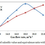 |
Figure 6: Variation of calorific value and equivalence ratio with gas flow rate Click here to View figure |
Variation of calorific value of producer gas with the gas flow rate is shown inFig. 6. Calorific values of the producer gas are increased with gas flow rate up to 18 m3h-1 and thereafter started declining. The calorific valuewere found as 3.80, 4.10, 4.35, 4.55, 4.39 and 4.20 MJm-3 at the gas flow rate of 12, 14, 16, 18, 20 and 22 m3h-1respectively. Calorific value of producer gas was found minimum (3.80 MJ m-3) at the gas flow rate of 12 m3/h. The reason perhaps may be that, at this gas flow rate, the equivalence ratio was quite low (less than 0.2) where pyrolys is process predominates and proper gasification process may not be taking place. The maximum calorific value of producer gas was obtained as 4.55 MJ m-3 at the gas flow rate of 18m3h-1. At this level of calorific value the equivalence ratio was found as 0.35. Thereafter, the calorific value of producer gas started declining. Perhaps, the reason may be the process converted towards combustion rather than gasification.
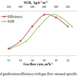
Variation of gasification efficiency with gas flow rateand specific gasification rate is shown in Fig.7.Values of gasification efficiency was found as 61.92, 64.02, 67.93, 71.05, 70.31and 67.90 % at the gas flow rate of 12, 14, 16, 18, 20 and 22 m3h-1respectively. The behavior is almost similar to that of the variation of calorific value with gas flow rate as shown in Fig.6. It can be seen from the Fig.7 that the maximum gasification efficiency of 71.05 % was found at the gas flow rate of 18m3h-1. Therefore, it can be safely said that the gasifier should be operated at 18 m3h-1gas flow ratefor maximum efficiency. At this gas flow rate maximum calorific value of 4.55 MJm-3 was achieved. Gasification efficiency was increased from 61.92 to 71.05 % as specific gasification rate increased from 122.9 to 192.51 kgh-1m-2. Further increase in specific gasification rate, the efficiency was reduced. This reduction in the efficiency at higher specific gasification rate was due to decrease in heating value of producer gas which could not perhaps be compensated by increasing gas flow rate. Therefore, the specific gasification rate of 192.51kgh-1m-2 provided the highest gasification efficiency of 71.05 % and calorific value of 4.55 MJm-3 respectively.
 |
|
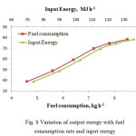
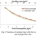
Variation of output energy with fuel consumption rate and input energy at different gas flow rate is shown in Fig. 8. Values of output energy was found as 38.76, 48.79, 59.16, 69.62, 74.63 and 78.54 MJh-1at the fuel consumption rate of 4.6, 5.6, 6.4, 7.2, 7.8 and 8.5 kgh-1 with gas flow rate increased from 12 to 22 m3h-1.It can be seen from the figure that the output energy is increased with increase in fuel consumption rate. Fig. 8 also shows that rate of increase in output energy is more up to the fuel consumption rate of 7.2 kgh-1,after that the rate of increase in output energy is less. This is perhaps the calorific value of producer gas increased with increase in fuel consumption rate up to 7.2 kg/h, after that the calorific value decreased with increase in fuel consumption rate. Values of input energy was 73.646, 89.656, 102.464, 115.272, 124.878 and 136.085 MJh-1 at the fuel consumption rate of 4.6, 5.6, 6.4, 7.2, 7.8 and 8.5 kgh-1 with gas flow rate increased from 12 to 22 m3h-1.Obviously, it can also be seen from the figure that the similar kind of trend is noticed in the variation of output energy with input energy to that with fuel consumption rate.
 |
|
Variation of percent residual char at different fuel consumption rate and different gas flow rate is shown in Fig. 9. Values of percent residual char was found as 23.91, 19.55, 17.06, 15.13, 13.95, and 12.78% (w/w) at the fuel consumption rate of 4.6, 5.6, 6.4, 7.2, 7.8 and 8.5 kg/h with gas flow rate increased from 12 to 22 m3h-1.It can be seen from the figure that the percent residual char is decreased with increase in fuel consumption rate and gas flow rate.The results of residual char in the present study were in accordance with the studies conducted by17 and reported that amount of residual char decreased from 28.96 to 16.33 % (w/w) with increase in gasification rate from 6 to 33 m3h-1.
 |
|
Economic Analysis
Economic analysis of the developed system was carried out for shredded cotton stalk as feed stock for thermal application and compared with briquette. Economics of the system was analyzed at the gas flow rate of 18 m3h-1at which the gasifier performed better in terms of gasification efficiency (71.05 %) and calorific value (4.55 MJh-1).The analysis was carried out for 270, 300, 330 days of operation per year and different operating hours per day i,e 12, 14, 16, 18, and 20 h. Economics of the system was examined by calculating net present value, benefit cost ratio, payback period and cost of operation. The capital statement of the gasifier system is given in Table 4.
Table 4: Capital statement for gasifier system
|
Sr. No. |
Particular |
Value |
|
|
Shredded Cotton Stalk |
Biomass Briquette |
||
|
1 |
Cost of the system, Rs. |
122000 |
63000 |
|
2 |
Life of the system, year |
10 |
10 |
|
3 |
Interest, % |
10 |
10 |
|
4 |
Depreciation, % |
20 |
20 |
|
5 |
Repair and Maintenance cost, % |
20 |
20 |
|
6 |
Electricity charges,` kWh-1 |
06 |
06 |
|
7 |
Light diesel oil cost,` lit-1 |
53 |
53 |
|
8 |
Labour cost, ` h-1 |
25 |
25 |
|
9 |
Cost of the feed stock, `kg-1 |
1.00 |
3.50 |
|
10 |
Shredding cost, ` kg-1 |
0.37 |
-- |
|
11 |
Transportation cost, ` kg-1 |
0.50 |
-- |
Economic indicators of the gasifier system considering shredded cotton stalk and briquette as feed stock is given in Table 8.It can be seen from the table that NPW for shredded cotton stalk as feed stock is 2.15 to 2.35 times more as compared to briquette at all the levels of operation days per year and operating hours per day. Table 5 shows that NPWof the gasifier system is increased from Rs.990203 to Rs.2144814 and Rs.457206 to Rs. 997896 for shredded cotton stalk and briquette as feed stock respectively with increase in operating days from 270 to 330 per year and operating period from 12 to 20 hours per day.It can also be seen from the table that BCRfor shredded cotton stalk as feed stock is more as compared to briquette at all the levels of operation days per year and operating hours per day. The BCR is ranged from 2.06 to 2.21 and 1.41 to 1.46 for shredded cotton stalk and briquette as feed stock respectively. Table 8 also shows that payback period is less for shredded cotton stalk, varying from 3 year 5 months to 3 year 8 months, as compared to briquette, varying from 5 year 9 months to 5 year 11 months, at all the levels of operating hours per day and operating days per year. The cost of the operation per hour (Rs.40.62) for shredded cotton stalk was also less as compared to the cost of operation for briquette(Rs.52.43). Therefore, it can be safely said that the developed gasifier system was more economical by using shredded cotton stalk as feed stock as compared to briquette.
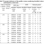 |
Table 5: Economic indicators of the gasifier system considering shredded cotton stalk and briquette as feed stock Click here to View table |
Conclusion
Gasification of shredded cotton stalk is successfully carried out by developing an open core throat less downdraft gasifier reactor.The maximum calorific value of producer gas was found as 4.55 MJ m-3.Maximum gasification efficiency of 71.05 % was found at the gas flow rate of 18 m3h-1 and specific gasification rate of 192.51 kgh-1m-2.The values of benefit cost ratio of the system operated by considering shredded cotton stalk are more as compared to the values obtained by using the briquette as feed stock. The values of benefit cost ratio of the system was increased from 1.45 to 2.18 (50.34%), 1.45 to 2.20 (51.17%) and 1.46 to 2.20 (51.36%) during 20 hours of operation per day for 270, 300 and 330 days of operation per year respectively by considering shredded cotton stalk as compared to the briquette as feed stock.Payback period of the system operated by considering shredded cotton stalk is less (40 %, during 20 hours of operation per day) as compared to the values obtained by using the briquette as feed stock. Therefore, from the experimental investigation and economic analysis, it can be safely recommended that the biomass gasification is more economical by considering shredded cotton stalk as compared to biomass briquette as feed stock.
Acknowledgements
The authors are grateful to the authorities of Junagadh Agricultural University, Junagadh (Gujrat), India for providing timely financial support to develop and test the gasifier system.
References
- Anonymous, Gujarat Agri Project, Sanskar Kendra, Paldi, Ahmedabad, November 21–24, 2002.
- Reed, T. B. and Das, A. Handbook of Biomass Downdraft Gasifier Engine System. The Biomass Energy Foundation Press, Colorado, 1984.
- Groveneveld, M. J. and Japp, J. Hos. Gasification of various wastes (1-50 mm) annular co-current moving bed gasifier. Proceeding of 2nd EL conference on Energy from Biomass. Applied Science Publisher, pp. 406-407, 1983.
- Kaupp, A. Gasification of rice husk: Theory and Praxis. Publication of Dt. Zentrum fur Entwickhings technologies; Wiesbaden; Vieweg, 1984.
CrossRef - Kaupp, A. and Goss, J.R Small-scale gas producer engine system. Published by GATE/GTZ, Germany, 1984.
- Bridgwater, A.V. Thermochemical processing of biomass. Editor Butterworth, UK ,1984.
- Jain, A. K. and Goss, J. R. Determination of reactor sealing factors for throatless rice husk gasifier. Biomass and Bioenergy, Vol. 18, pp. 249-256, 2000.
CrossRef - Tiwari, G., Sarkar, B. and Ghosh, L. “Design Parameters for a Rice Husk Throatless Gasifier Reactor,” Agricultural Engineering International: the CIGR Journal of Scientific Research and Development, Vol.8, 2006.
- Sims, R. Climate change solutions from biomass, bioenergy and biomaterials. Agricultural Engineering International: the CIGR Journal of Scientific Research and Development. Invited Overview. Vol. 5, 2003.
- Rathore, N. S., Panwar, N. L. and Vijay Chiplunkar, Y. Design and techno economic evaluation of biomass gasifier for industrial thermal applications, African Journal of Environmental Science and Technology Vol.3 (1), pp 6-12,2009.
- Kumar S. Fundamentals of renewable energy resources. Kalyani publishers, New Delhi, India, 2013.
- Jenkins, B. M. Downdraft gasification characteristics of major California based residue derived fuels. Unpublished Ph.D. Thesis, submitted UC Davis, 1980.
- Ramana, P. V., Singh, R. N. and Patil, K. N., Development and performance evaluation of a producer gas based system for hardening of steel. Renewable Energy, 30(5):773-782, 2005.
CrossRef - Singh, R. N., Jena, U., Patel, J. B. and Sharma, A. M. feasibility study cashew nut shells as an open core gasifier feedstock. Renewable energy, Vol. 31(4), pp. 481-487, 2006.
CrossRef - Jain, A. K. Design Parameter for Rice Husk Throat less Gasifier. Agricultural Engineering International: the CIGR Journal, Manuscript, Vol 8, 2006.
- Rajput, A. K., Performance studies on compression ignition engine using producer gas-diesel mixture as fuel, M.Tech (Agril. Engg.) Thesis (unpublished), PAU, Ludhiana, Panjab, 1998.