Hydraulic Design of Sewage Treatment Plant for Junagadh Agricultural University Campus
Vaibhav M. Ram1
*
 , Ajay D. Makwana2
and Dhaval S. Thanki3
, Ajay D. Makwana2
and Dhaval S. Thanki3
http://dx.doi.org/10.12944/CWE.13.3.20
The Junagadh Agricultural University campus is located in Junagadh, which lies in western Gujarat. The human population on the campus is multiplied distinctively due to the establishment of new schools and hostels.The university campus had a population of 1418 in the year 2013 when the supply of water was 152 lit/day per person and the sewage generation was 0.0084 m3/s (725.76 m3/day).Hence, a sewage treatment plant (STP) with suitable capacity is needed to deal with the elevated sewage. The recycled water can be utilized for agricultural purposes. This paper discusses about the design of STP and its major components such as skimming, grit chamber, and screening chamber, active sludge, sedimentation tank and secondary clarifier in the end sludge drying beds. The proposed design is suitable for 0.0672 m3/s sewage and would help to provide58 MLD process capacity. In the end, treated water will have been used for irrigation purpose in the research field of a university.
Copy the following to cite this article:
Vaibhav R, Ajay D. M, Thanki D. S. Hydraulic Design of Sewage Treatment Plant for Junagadh Agricultural University Campus. Curr World Environ 2018;13(3). DOI:http://dx.doi.org/10.12944/CWE.13.3.20
Copy the following to cite this URL:
Vaibhav R, Ajay D. M, Thanki D. S. Hydraulic Design of Sewage Treatment Plant for Junagadh Agricultural University Campus. Curr World Environ 2018;13(3). Available from: https://bit.ly/2Av09on
Download article (pdf)
Citation Manager
Publish History

Introduction
Water is one of the important and precious natural resources. Efficient use of water is important for agricultural production. At present, the use of chemical fertilizers in agriculture is increasing day by day but, the production of chemical fertilizers is lesser than its demand. Moreover, treated sewage water is rich both in organic matter and nutrients which fulfil the requirement of plants (particularly phosphorus and potash). It can be profitably utilized either as irrigation water or as a manure to supply nutrients to different crops.1
Sewage treatment is the procedure of disposing of contaminants, suspended solids from sewer water and domestic sewage, this material is sullied with several harmful natural and inorganic mixes.2 It is acomplicated combination ofbiological and physiochemical processes for removingphysiochemical and biological unwanted contaminates. Which can be cleaned by the STP. The STP’s mainfunction is to recycle effluent and the solid waste or slime a reasonable level of quality for release or reuse once again into nature.
It is estimated that about 38,254 million litres per day (mld) of wastewater is generated in urban area class I towns and class II cities having a populace of extra than 50,000 (accounting for more than 70 percent of the total urban population). The municipal wastewater treatment capacity developed up to now is about 11,787 mld, that is approximately 31% of wastewater generated in class I&II towns. The status of wastewater generation and capacity of sewage treatment plant developed over past ten yearsin urban Areas (Class I & II) is shown in Table 1. On the basis of population growth in this country. The Requirement of freshwater for all users will become out of control. it's far estimated that the projectedwastewater from the urban area may also pass 1,20,000 MLD via 2051 and that rural India will even generate not less than 50,000 MLDon the basis of water supply designs for community components in rural regions (see table 2).However, control plans of wastewater do no longer deal with this increasing pace of wastewater era.9
Table 1: Generation and Treatment of sewage Capacity in Urban Centres.
|
Parameters |
Class I cities |
Class II towns |
||||||||
|
1978–9 |
1989–90 |
1994–5 |
2003–4 |
2009 |
1978–9 |
1989–90 |
1994–5 |
2003–4 |
2009 |
|
|
Number |
142 |
212 |
299 |
423 |
423 |
190 |
241 |
345 |
498 |
498 |
|
Population (millions) |
60 |
102 |
128 |
187 |
187 |
12.8 |
20.7 |
23.6 |
37.5 |
37.5 |
|
Water Supply (mld) |
8638 |
15,191 |
20,607 |
29,782 |
44,448 |
1533 |
1622 |
1936 |
3035 |
3371 |
|
Wastewater Generated (mld) |
7007 |
12,145 |
16,662 |
23,826 |
35,558 |
1226 |
1280 |
1650 |
2428 |
2696 |
|
Wastewater treated (mld) (percent) |
2756 |
2485 |
4037 |
6955 |
11,553 |
67 |
27 |
62 |
89 |
234 |
|
Wastewater untreated (mld) (percent) |
4251 |
9660 |
12,625 |
16,871 |
24,004 |
1160 |
1252 |
1588 |
2339 |
2463 |
Table 2: Generation sewage from urbanareas and Projections for 2051.
|
Year |
Urban |
sewage |
Gross sewage |
|
1977–1978 |
72.8 |
116 |
7007 |
|
1989–1990 |
122.7 |
119 |
12145 |
|
1994–1995 |
151.6 |
130 |
16662 |
|
2003–2004 |
243.5 |
121 |
26254 |
|
2009 |
316.15 |
121 |
38254 |
|
2051 |
1000 |
121 |
120000 |
Sewage suggests to a collection of sewage water from involved regions andtransfers them to some point where it can dispose (at present there is no such conveying system exist within the campus area, which is required to be established). The fluid squanders would require remedy earlier than they're released into the water frame or in any other case disposed of without any harmful effect on peoples fitness or inflicting offensive conditions.6
In JAU campus present population is 1418 (with student and staff) by population forecasting method in 2042 population is 1888.Water supply to each person is 152 lit/day and sewage generation is 80% of water supply.3 As per calculation sewage discharge is 0.0084m3/s. This is not feasible as per cost and design. To run the plant for 24 hr with this discharge is not possible. So, the plant is needed more discharge. That means one receiver chamber is required for collecting 24 hr sewage discharge in that way plant is run in two shifts of 1.5 hr in a day.7 Proposal site for STP in JAU has shown in fig.1.
 |
Figure 1: The Proposed site for STP. Click here to view figure |
Materials and Methods
Location of Sewage Treatment Plant (STP)
Sewage treatment plant must be placed as near the land at such an area from wherein the dealt with sewage can immediately go with the flow under gravitational force closer to the disposal factor. The plant has to no longer be plenty a long way far from the sewage starting place to lessen the length of the sewer line.
Design
Sewerage treatment plant has also the external part which includes underground sewer pipes and builds STP treatment component, which can't be easily changed or accelerated in their capacities without difficulty or quite simply in near future. For avoided such conditioninthe future expansions of the campus and as well asexpansion within the sewage, amount ought to be forecasted to serve JAU satisfactorily for an affordable time. For the concern of future, some extra freeboard has provided in design so in next 30 year its component also work properly.Effluent realised from campus must meet the countrywide standards for wastewater set by Government authorities. So, Sewage Treatment Plant (STP) must design & operated in one of this manner that it treats the wastewater to those requirements.
Table 3: Test Report of sewage water samples of JAU Campus.
|
PARAMETERS |
RAW SEWAGE OF JAU campus |
EFFLUENT (expected) |
|
pH |
7.33 |
5.5-9.0 |
|
BOD |
106.87 |
≤ 20 ppm |
|
COD |
100.26 |
≤ 250 ppm |
|
Oil and Grease |
NA. |
≤ 5 ppm |
|
TSS |
33.04 |
≤ 30 ppm |
|
Nitrogen |
NA. |
≤ 5 ppm |
|
Ammonical Nitrogen |
NA. |
≤ 50 ppm |
|
Phosphorus (as PO4) |
NA. |
≤ 5 ppm |
|
Total Coli form |
5.29 x 10⁶ |
≤ 1000 no/100 ml |
Calculation of total Volume sewage generation
Design period consider 30 years lifespan.
Present population in 2012=1418
Forecasted population at 2042=1888
Water Supply Per Capita = 152 l/day
Avg. water supply per day = 1888 x 152
= 286976
= 0.28 MLD
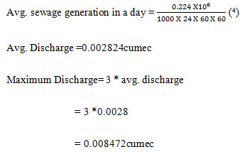
Avg. sewage generation per day is nearly 80% of supplied water.
= 0.8 *0.28
= 0.224 MLD
In cumec,
Points considered for design
Following points are taken into consideration throughout the layout of STP:
The design period has taken 30 years.
The Design was not done by an hourly flow of sewage generated. But it will consider all year avg, daily flow of sewage.
Rather than providing one high capacity component for every treatment more than two numbers small one to be provided, with a purpose to provide in operation in addition for the plant will not stop at upkeep and restore time.
For bypasses and Overflow, assembly should be kept in mind when designing every part.
Self-cleansing speed of flowmust create by design at each part in STP.
The design of the STP parts should be economical,maintenance free and flexible for an uncertain condition.
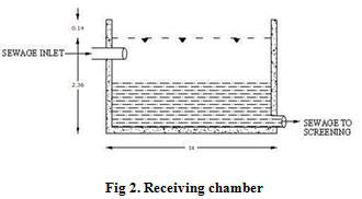
Design of receiving chamber
It is an oblong form tank made at the doorway of the STP. The main pipe which is pass sewage is directly passed sewage to this tank.
 |
|
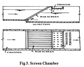 |
Figure 3: Screen Chamber |
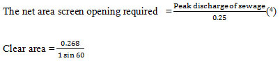
In this part row,sewage pass through different types of thescreen on the way to catch and removed off the floating matter together with tree leaves, fiber, rags, timber pieces, paper, gravel, tampons, and kitchen refuse and many others.
Design of Coarse screens
It includes metallic rodswhich is placed at 30° to 60° angle to the horizontal axis. Space betweenrods is 50mm or more. Thesegang of the rod is located inside the screen chamber at flow line of sewage.
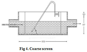 |
Figure 4: Coarse screen |
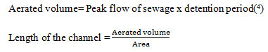
Design of Grit chamber
Grit removal chamber isworking on sedimentationprincipal. Which hasplaced in front of the fine screen. When the flow has pass through it will have removed inorganic particles having Sp.gravity of 2.65. The grit chamber designed like that which catches the lighter organic matter at simultaneously and heavier organic matter remainsin settled position.
 |
Figure 5: Aerated grit channel Click here to view figure |
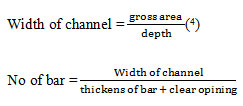
Design of Fine screen
Fine screens are the filtering system which isplaced between grit chambers and primary sedimentation tank which will take away a few quantities of suspended solids from sewage.
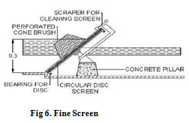 |
Figure 6: Fine Screen Click here to view figure |
Design of skimming tank
Skimming tanks are the tanks getting rid of oily material from the sewage built earlier than the sedimentation tanks. In skimming tank, air flow entering from the side and chlorine gas with the aid of air diffuser positioned from the bottom of the tank. Because of air rise tends to solidify and coagulate the grease and motive it to upward push to the top of the tank whereas chlorine gasoline destroys the protective combination impact of macromolecule that holds the grease in mixed form.

Where,
Vr = Min rising velocity of the oily material to be removed in m/min.
q = sewage flow rate in m3 / day.
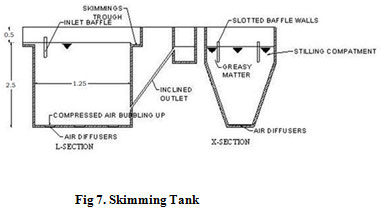 |
Figure 7: Skimming Tank Click here to view figure |
Design of Primary sedimentation tank
Primary sedimentation tank is working like settling of heavy mater so that it is called a settling tank. Which was placedafter skimming tank so that eliminate the natural solids that are too heavy to be removed i.e. the debris having sizelover then 0.2 mm and Sp.G of 2.65 and also built inclined plate clarification, those by use of gravityclarifiers work alongside the projected settling region as a manner to have an impact on a fairly immoderate percentage of elimination of suspended solids as 60 to 65% of total TSS and 30 to 35% of the BOD from the Row sewage.
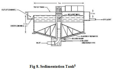 |
Figure 8: Sedimentation Tank Click here to view figure |
Design of Secondary sedimentation tank
Secondary sedimentation tank place at after aeration tank it's far known as secondary sedimentation. This tank is wished because of the number one sedimentation tank with high-quality adjustments as no floating substances are right here, provisions for the elimination of scum, floatage aren't desired.5
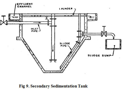 |
Figure 9: Secondary Sedimentation Tank |
Design of Sludge drying beds
In this Drying processes of semisolid digested sludge on open-air beds on the land is call sludge drying and such system of open beds drying is call sludge drying beds. Moisture containssemisolid digested sludge is highwhich is comesfrom digestion tank. So it is required to dehydrate the digested sludge before it disposed of or dump somewhere.
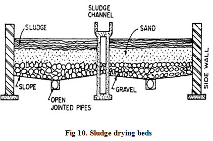 |
Figure 10: Sludge drying beds |
Results
According to the survey, the population of the JAU campus is 1418 persons in the year 2012, and it is expected to 1888 persons in the year 2042 as per assumed 10% incremental growth. It is found that the domestic water supply within JAU campus is about 0.432 MLD as per study of water supply survey. It is also worked out in sewage water survey that sewage flow rate is 0.0084m3/s; which is very low sewage discharge. The care has been taken in the said design of STP to fulfill the requirement of standard design, but looking to the discharge and quality of sewage water the designed plant is not economically feasible, so it is suggested that the additional sewage water should be channelized to the aforesaid STP, to have cost-effectiveness and efficiency of plant.
To handle this low discharge, one circular collecting chamber is designed admeasuring 14m diameter and 2.50 m. deep, which collects the sewage water throughout the day and collected sewage water discharged to said STP, by means of this collecting chamber the discharge to STP can be maintained. So it is required that, the plant run in two shift for 1.5 hours which results in 0.0672 m3/s discharge within STP.
Table 4: Design details.
|
Component |
TYPE |
NOS |
DIMENSIONS |
|
Receiving chamber |
|
1 |
14 m ØX 2.36 m (SWD) + 0.14m (FB) |
|
Coarse screen |
1 mechanical |
1 |
0.51X 0.7m (SWD) + 0.3 m (FB) |
|
Grit chamber |
Horizontal Flow type |
1 |
1.2m X 5m X 2.5m |
|
Fine screen |
Disc type, Mechanical |
1 |
97 nos. of bar,3 mm thickness of bar, 0.3 m(SWD),0.58 m periphery of disc |
|
Skimming tank |
Air diffuser + Chlorine gas |
1 |
25m X 0.90m X 2.5m + 0.5m (FB) |
|
Secondary clarifier |
Circular type, Radial flow |
1 |
6m dia X 3.5m (SWD) + 0.5m (FB) |
|
Sludge drying bed |
Sand + Gravelled |
2 |
1m X 1.25m |
Conclusion
Wastewater treatment includesa variety of processes performed at different levels of treatment. The essential type of treatment is the separating of natural waste by microscopic organisms either vigorously or anaerobically or a mix of both which happens in optional treatment. Essential treatment offers the settlement of solids. Tertiary treatment includes the evacuation of phosphorus, nitrogen and toxic substances. Pathogen expulsion happens all through treatment yet turns out to be more compelling for the most part at tertiary levels using UV beams and chlorination. The higher the treatment productivity the better quality of effluent produced.
As per design point of view first, construct sewage collating at Hostel area and staff residential area which convey wastewater to STP timely and efficiently and also provide to a facility of repair and maintenance and also keep in mind future expansion.
As per the design point of view, discharge is very low so, the plant cannot run 24-hr. Therefor STP run only 3-hr in a day and provide an extra construction of collating chamber.
Running of more than 3-hr in a day for decrease operating cost and increase saving of electricity of pumping irrigation water.
Acknowledgment
We are especially thankful to Junagadh Agricultural University who gave funding and golden opportunity to complete this research work on Hydraulic Design of Sewage Treatment Plant for Junagadh Agricultural University Campus, which also helped us in doing a lot of work in the research area and also to know about many new things in this particular research. Secondly, we are also thankful to Prof. D.S Thanki and Mr. Viral Vora who helped us a lot in finalizing this research.
References
- Afifi. Ahmed A., Kh. M. Abd El-Rheem, and Refat A. Youssef, ‘Infl uence of Sewage Water Reuse Application on Soil and the Distribution of Heavy Metals’. Nature and Science. (2011);9(4),82–8.
- Aswathy, M. and Hemapriy., ‘analysis and design of sewage treatment plant (stp) of appartments in chennai.’. International Journal of Pure and Applied Mathematics. (2017);116(13),157-163.
- Bhardwaj, Rajendra M., ‘Status of Wastewater Generation and Treatment in India’, Paper presented at Intersecretariat Working Group on Environment Statistics (IWG–Env) Joint Work Session on Water Statistics, Vienna, (2005);20–22.
- Garg, S.K. Sewage diposal and air pollution engineering vol-II, Khanna publishers. (1996).
- Gladis, R. Influence of waste water irrigation and graded levels of N and P on soil properties and response of fodder sorghum (var. Co. 27). M.Sc., (Ag.) Thesis, TNAU, Coimbatore-3: (1995).
- Mara, D., ‘Design Manual for Waste Stabilization Ponds in India’, University of Leeds, England, available at http://www.leeds.ac.uk/civil/ceri/water/tphe/publicat/spwarm/wspwarm.html Last accessed in June 2011. (2009).
- Ministry of environment, forest and climate change(GOI) ‘feasibility reportonsewage treatment plant,Proposed Residential Apartment project by Smt. H Shailaja, Sy. No. 186/4, Kaggadasapura Village, Varthur Hobli, Bangalore East Taluk, Bengaluru Urban District: (2014).
- https://www.slideshare.net>anup_shres007.
- Young, C. E.; and D. J. Epp. Land treatment of municipal wastewater in small communities. American Journal of Agricultural Economics. (1980);62(2),238-243.
CrossRef