MPPT for Photovoltaic System Located in Latakia Province - Syria by Using Genetic Algorithm
Hassan Kenjrawy1
, Carlo Makdisie1
, Issam Housamo1
and Hassan Haes Alhelou1, 2, 3
*

http://dx.doi.org/10.12944/CWE.14.1.16
Copy the following to cite this article:
Kenjrawy H, Makdisie C, Housamo I, Alhelou H. H. MPPT for Photovoltaic System Located in Latakia Province - Syria by Using Genetic Algorithm. Curr World Environ 2019;14(1). DOI:http://dx.doi.org/10.12944/CWE.14.1.16
Copy the following to cite this URL:
Kenjrawy H, Makdisie C, Housamo I, Alhelou H. H. MPPT for Photovoltaic System Located in Latakia Province - Syria by Using Genetic Algorithm. Curr World Environ 2019;14(1). Available from: https://bit.ly/2H3wvKD
Download article (pdf) Citation Manager Publish History

Introduction
Renewable energy is not only an alternative clean and environmentally friendly source of energy, but rather it is a real need especially during large scale crisis due to the possibility of its local control and operation.
Photovoltaic (PV) systems, among other renewable and new energy sources, can be considered as the most available renewable source in Syria. However, maximum harvested energy due to the nonlinearity in PV module characteristics of PV system is not fixed, but rather it varies depending on several factors, such as incident of solar radiation (static placement of solar panels limits their area of exposure to the sun), temperature, load condition, DC/DC converter output voltage, and weather condition.1 Therefore, in order to maximize the energy extraction of photovoltaic systems under different operating conditions, tracking systems are needed to track both solar radiation (solar tracking) and maximum energy point (MPPT) tracking in relation to solar radiation.2
A thorough review of the literature reveals that several methods (techniques) for sun tracking, MPPT tracking, and the combination of both have been developed over the past few decades.
Tracking Techniques
A microprocessor-based automatic sun-tracking system is proposed in reference3 to control the movement of a solar panel to track the motion of the sun. Determining the maximum angle for the panel in both positions (east and west) is done using two limited switches linked to it. The status, reaching the maximum angular positions in either direction has been reached, is analyzed by a microprocessor and deiced that panel shouldn’t change its positions furthermore. As a result, maximum thermal energy is achieved, by keeping the position of the panel at the normal direction of the sun. A new micro-controller based solar-tracking system is proposed in reference.4 The presented system organizes to check the position of the sun and control the related movement of the panels to have the best radiation from the sun on the surface of the solar panel. In addition, it can work independently to set up a geographical location. A tracking system based on a computer controller that drives a DC motor with permanent magnets is done to maximize the out power of PV panel by moving it in two axesin.5 To achieve the optimal position for the panel, solar tracker with the low-cost feature was designed and tested its capacities on an experimental prototype in reference.6 This tracker was based on a PC fuzzy logic control algorithm and error signal. In addition, different kind of control strategies was applied such as the traditional ones “PID” and the upgraded ones “Fuzzy logic control”. a tracking self-cleaning system was designed and applied by a stepper motor and gearbox which controlled by 8051 microcontrollers is presented in reference.7 For sun tracking, this technique has no requests for any sensor or synchronization. A novel two-axis tracking system with external light sensors to direct the panel to the maximum position of the sun is proposed in reference.8 The proposed system increases the efficiency by using the solar panel as the sensors. In ref.,9 a genetic algorithm (GA) is suggested in order to enhance the performance of PV panels. The parameters of GA were calculated to optimize a solar tracking system. Comparing different axis for sun tracking were done in.10
An automatic sun-tracking system was upgraded by introducing a new control technology depends on stepper active tracker.11 This technology applied by a microprocessor. The designed system has many advanced characteristics for protection and reliable anti- disturbance functions.
A closed-loop technique to control a tracking system for PV panel has been done in Reference.12 This system is a dual axis hybrid type and acts as a sensor so it can follow the sun continuously. an additional feed-forward control loop was added to the closed one to improve the tracking efficiency of the solar panel. The trajectory of the sun is used to manage the rotation angle of PV for the feed-forward tracking objective.13
For multiple dual-axis (PV) panels, the solar tracking control method is used.14 The photoelectric sensor is used to detect the signal in this paper and different models of tracking system with two degrees of freedom. The distributed adaptive dynamic surface (DCS) control method is used. Light intensity as a foundation for tracking system and a comparison with a fuzzy logic intelligent method is used in reference.15 The main controller in this paper was Arduino UNO microcontroller and a four Light Dependent Resistor (LDR) sensors were added for sensing the maximum incident intensity of solar irradiance. a real electronic device for controlling and driving a bi-axial solar tracker system for PV panel is presented in reference,16 this model is managed by a PC software application with a user-friendly graphical interface, and it has the ability to calculate the sun circadian orbit so, the panel's surface always perpendicular to solar rays. This process will improve the efficiency of energy extracted.
Reference3 conjugates the simple Perturb-and-Observe (P&O) MPPT technique with Sun tracker provided with light sensors. This proposed tracker gives a freedom movement in two axes by adding a two-degree mechanical mainframe that supports the PV. Reference9 presents a fuzzy active controller to track the maximum power point for solar panel dual-axis Sun. this controller will help the panel to orient the solar panel toward the Sun. as a result, this will enhance the efficiency of the PV generation system.
To improve the performance of the photovoltaic cell, a system using the two-axis solar tracking was introduced next to the maximum MPPPT target in.10 It also offers a step-by-step incremental, variable-speed conductive algorithm to meet dynamic response and stability requirements. The MPPT algorithm is designed to maintain a PV system that works in MPPT, while solar tracking technology is designed to track the sun both the azimuth angle and the elevation angle in order to enable solar panel perpendicular to sunlight.
In conclusion, the use of the traditional Sensor method for the photovoltaic plant won’t provide an ideal tracking to the Sun's place and position when intensity illumination is low. Also, the problem of malfunction of the tracking system by the very fast changing climate would rise.
Maximum output power of PV-system methodology
To harvest maximum output power of PV systems, Sun tracking mechanism and maximum power point tracker (MPPT) algorithm must be developed and utilized. Sun tracking mechanism guarantees that the solar panel keeps tracking the Sun in such a way that the solar irradiation is always normal to the panel surface. While the MPPT algorithm insures that the harvested power corresponding with each irradiation level is maximized. Therefore, the altitude and azimuth angles of the Sun (the position of the sun), as shown in Figure1 for any given time and date in the year must be determined Based on these angles and other parameters, the solar irradiation can be calculated easily.
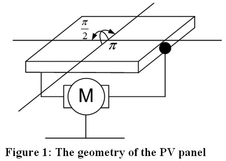 |
Figure 1: The geometry of the PV panel Click here to view Figure |
Sun tracking technique and solar irradiation calculation
Sun Tracking technique
Solar tracking means always keeping solar panels (at any time and date) oriented to the sun so that solar radiation is always vertically on the surface of the plate to collect the maximum solar radiation. Keeping solar panels always oriented towards the sun means that we must calculate the angles of the sun's rise and its name (the position of the sun) for any particular time and date of the year. Therefore, for achieving continuous Sun tracking which yields to maximum solar irradiation, we proposed the follow algorithm:
2. For any specified day, of the year, and specified time of that day, we have to choose the number of the day (as a number between 1 and 365) and the specified time (0-23).
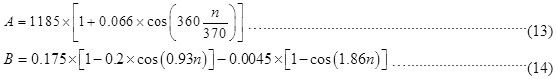
3. Based on the day number, the declination angle can be calculated from the following equation
n: is the number of the day
4. Determine the solar time using the following equation (The day time is not constant throughout the year (increased or decreased with a certain number of minutes):

Where:
where LSt is the solar time, Lt is the local time, LS is the reference Longitude line, L is the local Longitude line, and Et is the time equation.

Dt: is the summer or winter time change (increase or decrease by 1 hour).
After calculating the solar time in hours and minutes we convert it into degrees.
Day time changes in minutes as shown in Figure 2.
 |
Figure 2: The circuit diagram of the PV model Click here to view Figure |
5. Determine the hour angle using the following equation:

6. Determine the altitude angle using the following equation:

7. Determine the zenith angle using the following equation:

8. Determine the azimuth angle using the following equation:

9. Determine the Sun rising angle using the following equation:

10. Determine the day time hour's number using the following equation:

Applying the above-mentioned algorithm allows us to determine the position of the Sun at any given time and date in the year. Therefore, we can orient our solar panels towards the Sun at that time and date in order to collect the maximum solar irradiation.
After determining the Sun position, we can calculate the solar irradiation by applying the following algorithm:
Solar Irradiation Calculation
Solar irradiation consists of three components:
- Direct radiation on the inclined surface
- Diffused radiation scattered by the atmosphere
- Reflected radiation due to the terrestrial surface

Where:
qi : Is the angle between the sun's radiation and the vertical line on the surface of the board. Since the surface of the board is always oriented towards the sun, then qi = 0 and cosqi = 1
H Bn: is the solar radiation [W/m2]
A: is theoretical solar radiation with air density of zero [W/m2]
B: Atmospheric mitigation factor
g : Altitude angle of the Sun
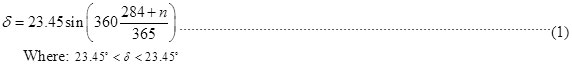
Changes in A and B values depend on the annular change of the distance between the Sun and the earth and the seasonal change of atmospheric humidity and other components. A and B and the can be determined from ASHRAE' tables for any specified month. Also, they can be calculated for any given day in the year using the following equations:
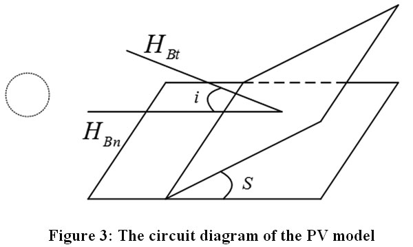 |
Figure 3: The circuit diagram of the PV model Click here to view Figure |
2. The diffused radiation scattered by the atmosphere is calculated using the following equation:

Where:
C: is the diffuse (scatter) factor
3. The reflected radiation due to the terrestrial surface is calculated using the following equation:

Where:
rg: is the reflection factor of the earth and usually, its value is
4. The total solar irradiation is calculated using the following equation:

Figure 4 shows the flow chart to calculate sun angles and solar radiation mentioned in the equations above
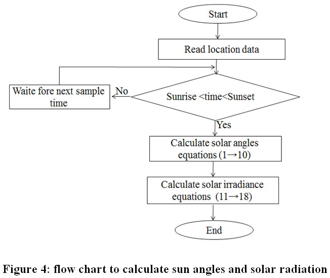 |
Figure 4: flow chart to calculate sun angles and solar radiation Click here to view Figure |
MPPT based on GA
GA is defined as a kind of randomized method of research that relies on the mechanism of natural choosing and optimization. Moreover, it achieves an optimal global level by combining job evaluation with random exchange and/or well-organized information between solutions. One of the key characteristics of GA is superior performance in nonlinear spaces compared to other optimization methods. Figure (5) illustrates the flow chart of the General Assembly.
For photovoltaics, the simplest solar cell model was adopted. In this model, the equivalent circuit of the solar cell is made up of a current source parallel to the diode as shown in Figure 5. A moment that corresponds to the output of the current and the light directed to the cell. The I-V properties of the cell are determined by the diode in the circuit.17 The model included both temperature dependence of the photo-current IL and the saturation current of the diode I0. In addition, the RS resistance series was used instead of conversion resistance. The diode is used in addition to a combination of diode quality factors in order to achieve the best curve match.
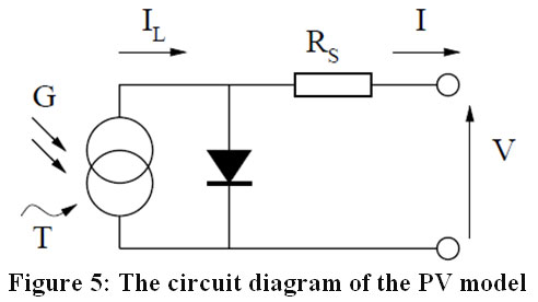 |
Figure 5: The circuit diagram of the PV model Click here to view Figure |
Where G is the irradiation level (W/m2), T is the temperature in (C°), IL is the photo-current (A), I is the output current (A), and RS series resistance (W).
The output current of this model is given (Shockley equation) as:

where I0: is the reverse saturation current of the diode, k: is Boltzmann constant, q: is the electron charge(Coulomb), T: is the temperature ºK, and n: is diode ideality factor.
GA has been applied in this paper as follows:
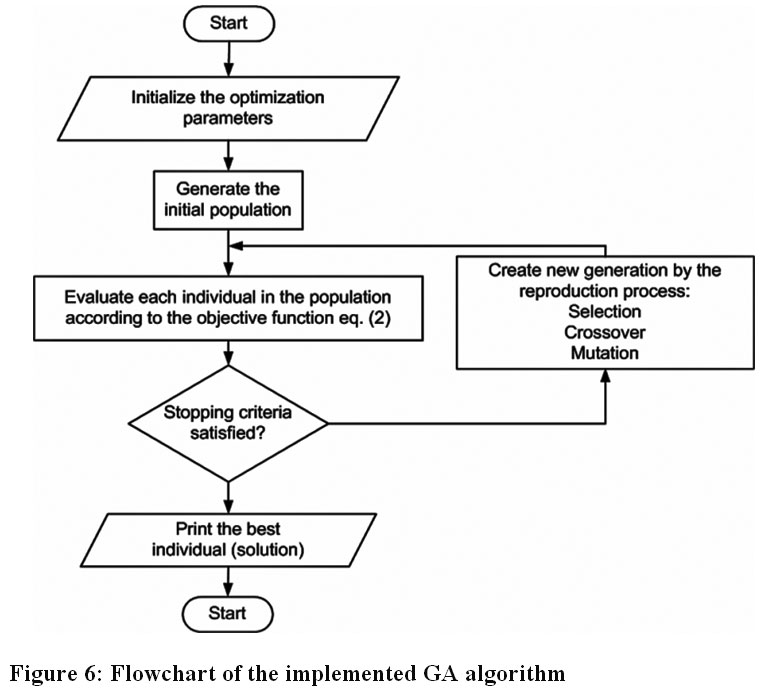 |
Figure 6: Flowchart of the implemented GA algorithm Click here to view Figure |
Step I: Input initialization
This includes optimization inputs (such as population size, the maximum number of generation, crossover method and probability, mutation method and its probability, stopping criterion, etc) and solar cell related data.
Step II: generation of the initial population
In order to consider the variables that should be optimized (the voltage and current of the solar cell), a random initial population of floating individuals of finite length is created. Each of these individuals concatenated of two chromosomes representing the feasible solution to the problem.
The first chromosome contains the value of the voltage which randomly generated in the range (0 £ V £ V OC), while the second chromosome contains the value of the current which randomly generated in the range (0 £ I £ I SC). The initial population is created in such a case by repeating these processes as much as the selected population size.
Step III: Fitness evaluation
The fitness of each independent solution of the initial generation is analyzed by determining the maximum value of the objective function.
Step IV: Creation of a new generation
A new population is created with the elimination of the worse performing individuals, whilst the most highly fit members are selected to pass on information to the next generation.
This includes three main processes, selection, crossover, and mutation. The adopted functions for these processes are deterministic sampling selection, simple crossover with probability PC, and mutation operation with probability PM, respectively.
Step V: Repeating the process
Operation of selection, crossover, mutation, and evaluation are repeated until an optimum solution is achieved or the number of generation is reached.
Step VI: Ending process
The stopping standard is the maximum number of generations. If this number is achieved, stop the process and print the optimal solution.
Simulation Tools, Data and Results
Simulation and Data
The suggested MATLAB programs are developed to calculate the sun's elevation angles, the azimuth ratio, the solar irradiation calculation, and the GA-based maximum power point calculation for photovoltaic panels, then the all previous parameters will be used later for analytical purposes in this research.
To confirm the effectiveness and performance of the proposed methodology, advanced algorithms were tested on the SPK200GT solar panel. The data of this solar panel are taken from reference.22 The temperature is taken as 25°C.
Simulations are carried out on Pentium IV, 2.66 GHz, and 1GB of RAM computer. The initial parameter values of the implemented GA algorithm are shown in table 1.
Table 1: initial GA parameter values
|
GA parameters values |
|
|
Number of parameters |
2 |
|
Length of each independent solution |
3 |
|
generation size of solutions |
30 |
|
Most significant number of generation g max |
100 |
|
Number of progeny / pair of parents |
1 |
|
Selection probability Ps |
0.8 x population size |
|
probability Crossover Pc |
0.8 x population size |
|
probability Mutation Pm |
0.8 x population size |
Latakia city is located on the coordinates: Latitude: 35° 31¢ 23² and longitude 35° 47¢ 28².
Simulation Results
The developed methodology is programmed in Mat lab environment. Date and time are used as the only required inputs in order to calculate the results. Then, the program will calculate all the required results. These results include the settings of the solar panel angles (orientation angles, elevation, Zenith, and azimuth), the maximum irradiation corresponding to the settings, and the maximum output power of the solar panel.
Due to the maximum limitation policy of pages per one paper, it's not possible to present all the results that have been obtained. Therefore, some of the results have been presented in this paper the results presented here are just some samples of the results we have gotten where dates and times in these results were arbitrarily chosen.
Four different dates in different seasons, January 10th, April 10th, July 10th, and December 16th of one calendar year and different times for each day. The obtained results are presented as follows:
For n=10 (January 10th), 8:00 am:
For this specified date, the simulations were carried out for 8:00 am in the morning. The altitude (elevation), Zenith, and azimuth angles were determined according to ASHRAE to keep the solar panel surface perpendicular to the Sun radiation which ensures that the panel can receive the maximum solar irradiation for that particular time. Secondly, the maximum solar irradiation is calculated as indicated previously. Finally, the calculated value of the solar irradiation, corresponding to the specified time, is passed to the GA-based maximum power point (MPP) algorithm to calculate the MPP value. Therefore, the maximum output power of the solar panel corresponding to that specified time is achieved.
Table 2 shows the determined elevation, zenith, and the azimuth angles in degrees the calculated total solar irradiance in W/m2, and the obtained maximum output power in W along with the corresponding MPP voltage.
Table 2: The determined values on January 10th(n=10) at 8:00 am.
|
Elevation angle |
11.7º |
|
Zenith angle |
78.3º |
|
Azimuth angle |
-51.7º |
|
Solar irradiance (W/m2) |
652 |
|
Maximum Power - Pmax (Watt) |
128.7 |
|
Maximum Power Voltage - Vmpp (Volt) |
25.55 |
Figure 7 shows The P-V feature of PV corresponding to the determined value of the solar irradiance.
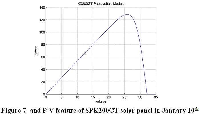 |
Figure 7: and P-V feature of SPK200GT solar panel on January 10th Click here to view Figure |
For n=100 (April 10th), at 12:00 pm:
The elevation, zenith, and the azimuth angles in degrees, the total solar irradiance in W/m2, and the maximum power of output in W are shown in table 3. The P-V feature of the solar panel is also shown in Figure 8.
Table 3: the determined values on April 10th (n=100) at 12:00 pm
|
Elevation angle |
60.6º |
|
Zenith angle |
29.4º |
|
Azimuth angle |
-19.8º |
|
Solar irradiance (W/m2) |
1035.8 |
|
Maximum Power - Pmax (Watt) |
207.4 |
|
Maximum Power Voltage - Vmpp (Volt) |
26.33 |
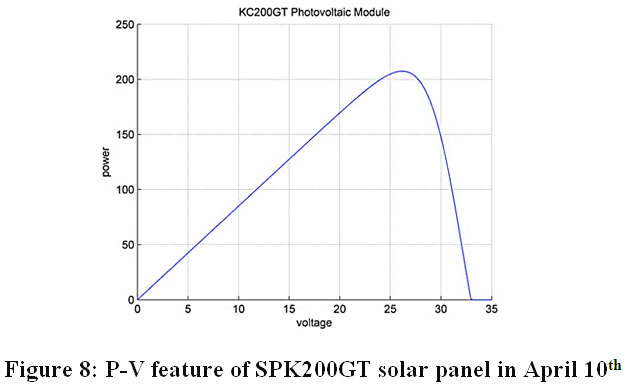 |
Figure 8: P-V feature of SPK200GT solar panel on April 10th Click here to view Figure |
For n=190 (July 10th), at 16:00 pm:
Table 4 shows the determined elevation, zenith, and the azimuth angles in degrees, the calculated total solar irradiance in W/m2, and the obtained maximum output power in W along with the corresponding MPP voltage.
Table 4: the determined values on July 10th (n=191) at 16:00 pm
|
Elevation angle |
45.1º |
|
Zenith angle |
44.9º |
|
Azimuth angle |
86.6 |
|
Solar irradiance (W/m2) |
918.3 |
|
Maximum Power - Pmax (Watt) |
183.3 |
|
Maximum Power Voltage - Vmpp (Volt) |
26.03 |
The P-V feature of PV panel corresponding to this value of the solar irradiance is shown in Fig 9.
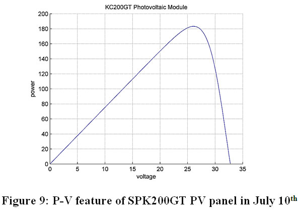 |
Figure 9: P-V feature of SPK200GT PV panel on July 10th Click here to view Figure |
For n=350 (December 16th ), at 16:00 pm:
The determined elevation, zenith, and the azimuth angles in degrees, the calculated total solar irradiance in W/m2, and the obtained maximum output power in W along with the corresponding MPP voltage are shown in table 5.
Table 5: the determined values on July 10th (n=350) at 16:00 pm
|
Elevation angle |
3.7º |
|
Zenith angle |
86.3º |
|
Azimuth angle |
57.6º |
|
Solar irradiance (W/m2) |
146 |
|
Maximum Power - Pmax (Watt) |
26.9 |
|
Maximum Power Voltage - Vmpp (Volt) |
24.1 |
The P-V feature of the panel corresponding to this value of the solar irradiance is presented in the Figure10.
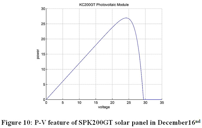 |
Figure 10: P-V feature of SPK200GT solar panel on December 16th Click here to view Figure |
These previous figures show that the maximum output curves vary from day to day. This value changes from minimum value (26.9W) at 16:00 (4:00 pm) on December 16th to maximum value (207.4 W) at 12:00 on April 10th.
After that, it can be concluded that there is a real need to follow the Sun and MPP tracking of the PV. Otherwise, the output power of the panel will not be maximized.
Figure 11 shows the maximization of the objective function (the output energy of PV) by GA algorithm. The output power of the solar panel is maximized using the GA algorithm after determining the accurate elevation and azimuth angles of the Sun and the corresponding solar irradiation to these angles at specified time and date. The Only case corresponded to maximum output power is presented in (n=100, April 10th).
 |
Figure 11: The convergence feature of the objective function by GA for maximum output power. Click here to view Figure |
Figure 12 shows the mean fitness feature of the objective function by GA for maximum output power case.
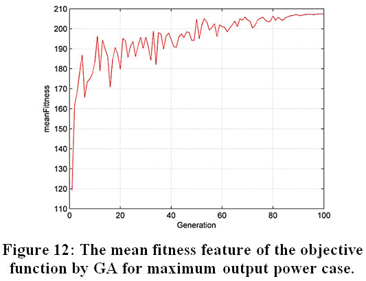 |
Figure 12: The mean fitness feature of the objective function by GA for maximum output power case. Click here to view Figure |
The results show; through the equations mentioned above we can achieve accurate sun tracking, and the genetic algorithm showed of large and infinite accuracy in of maximum power point tracking in the PV systems, thus contributing to increasing the efficiency and reliability of photovoltaic systems.
Conclusion
The maximum output power of PV can be achieved in photovoltaic systems for any given time and date by proper solar tracking and the maximum energy point of the panel. Sun tracking (height and azimuth angles) can be achieved by accurately calculating these angles. Identifying these angles ensures that maximum solar irradiance is received by the surface layer of PV panels. After calculating the solar radiation received, the maximum power point of the solar panel can be improved using a powerful enhancement technique such as GA. Therefore, the maximum solar energy output of PV solar panel can be determined for any time and date. The GA algorithm can easily and quickly and accurately achieve the maximum energy point of the solar panel even for very small levels of solar radiation. This methodology provides a complete set of data for any design of a separate or continuous control system to direct the solar panel towards sunlight. Additional development may include studying the impact of weather and other atmospheric conditions on the amount of solar irradiance received by the surface layer of PV panels.
In coming research a comparison between two algorithms could be done to show the accuracy and the high performance of each one to achieve the optimum selection. This study could be continued Considering the temperature is a variable parameter, to obtain the effect of this parameter on the efficiency of the PV panels.
Acknowledgements
The authors declare that this paper has not received any foundation and they do not have a conflict of interest. The authors are grateful to the national electrical company for providing the real data that helped them for concluding this research without any finance.
References
- S. Mashohor, Kh. Samsudin, Amirullah, M. Noor, A. A. Rahman, “Evaluation of Genetic algorithm based solar tracking system for photovoltaic panels", ICSET, pp. 269-273, 2008
CrossRef - S. Hadji, F. Krim, J. P. Guabert, "Development of an Algorithm of Maximum Power Point Tracking for Photovoltaic Systems Using Genetic Algorithms" IEEE USA, pp. 439-449, 2011
CrossRef - T. Esram and P. L. Chapman, "Comparison of Photovoltaic array maximum power point tracking techniques, IEEE transaction on energy conversion”, Vol. 22, No. 2, 2007
CrossRef - B. Koyuncu and K. Balasubramanian, " A microprocessor controlled automatic sun tracker", IEEE Transactions on Consumer Electronics, Vol. 37, No. 4, pp. 913–917, 1991.
CrossRef - O. Bingol, A. Altinta, and Y. Oner, "Microcontroller based solar-tracking system and its implementation", Journal of Engineering Sciences, Vol. 12, pp. 243–248, 2006.
- H. A. Yousef, "Design and implementation of a fuzzy logic computer-controlled sun tracking system,” IEEE International Symposium on Industrial Electronics (ISIE), Vol. 3, pp. 1030–1034,1999.
- A. Yazidi, F. Betin, G. Notton, and G. A. Capolino, "Low cost two-axis solar tracker with high precision positioning”, International Symposium on Environment Identities and Mediterranean Area (ISEIMA), pp. 211–216, 2006.
CrossRef - R. Tejwani and C. S. Solanki, "360° Sun tracking with an automated cleaning system for solar PV modules", 35th IEEE conference on photovoltaic specialists (PVSC), pp. 002895-002898, 2010.
CrossRef - S. Dasgupta, F. W. Suwandi, S. K. Sahoo, and S. K. Panda, "Dual-axis sun tracking system with PV cell as the sensor, utilizing hybrid electrical characteristics of the cell to determine insolation", IEEE International Conference on Sustainable Energy Technologies (ICSET), pp. 1-5, 2010.
CrossRef - A. H. Niasar, Z. Zare, and F. R. Far, "A low-cost P&Q based maximum power point tracking, combined with two-degree Sun tracker", 6th IEEE conference on Power Electronics, Drives Systems & Technologies, pp. 119-124, 2015.
- M. Suthar, G. K. Singh, and R. P. Saini, "Performance evaluation of Sun tracking photovoltaic study", Fifth IET International Conference on Advances in Recent Technologies in Communication and Computing (ARTCom), pp328-335, 2013.
CrossRef - J. F, Lee, N. A. Rahim, "Performance comparison of dual-axis solar tracker vs static solar system in Malaysia", IEEE conference on Clean Energy and Technology (CEAT), pp. 102-107, 2013
CrossRef - W. C. Sheng, W. Y. Bo, L. S. Yang, P. Y. Chang, and X. H. Hua, "Study on automatic Sun-tracking technology in PV generation", IEEE international conference on Electric Utility Deregulation and Restructuring and Power Technologies (DRPT), pp. 2586-2591, 2008.
- H. C. Lu and T. L. Shih, 'Fuzzy system control design with application to solar panel active dual-axis Sun tracker system", IEEE Conference on Systems, Man and Cybernetics (SMC), pp. 1878-1883, 2010.
- H. Li, C. Zhao, H. Wang, S. Xie, and J. Luo, " An improved PV system based on dual axis solar tracking and MPPT", IEEE Conference on Mechatronics and Automation, pp. 204-209, 2014.
CrossRef - M. S. Munna, M. A. I. Bhuyan, K. M. Rahman, and M. A. Hoque, "Design, implementation and performance analysis of a dual-axis autonomous solar tracker", 3rd IEEE conference on Green Energy and Technology (ICGET), pp. 1-5, 2015.
CrossRef - www.kyocerasolar.com/assets/001/5195.pdf, on September 6th, 2016.