Performance Evaluation of Split Air Conditioner with Consideration of Pressure Drop in Evaporator and Condenser
Punit Mishra1
*
 , Shubham Soni2
and Govind Maheshwari3
, Shubham Soni2
and Govind Maheshwari3
1
Mechanical Engineering Department,
Shri G S Institute of Technology and science,
Rajiv Gandhi Prodyogiki Vishwavidhyalaya,
Indore,
Madhya Pradesh
India
2
Mechanical Engineering Department,
Medicaps University,
Indore,
Madhya Pradesh
India
3
Mechanical Engineering Department,
Institute of Engineering and Technology,
Devi Ahilya Vishwavidhyalaya,,
Indore,
Madhya Pradesh
India
http://dx.doi.org/10.12944/CWE.17.3.8
Copy the following to cite this article:
Mishra P, Soni S, Maheshwari G. Performance Evaluation of Split Air Conditioner with Consideration of Pressure Drop in Evaporator and Condenser. Curr World Environ 2022;17(3). DOI:http://dx.doi.org/10.12944/CWE.17.3.8
Copy the following to cite this URL:
Mishra P, Soni S, Maheshwari G. Performance Evaluation of Split Air Conditioner with Consideration of Pressure Drop in Evaporator and Condenser. Curr World Environ 2022;17(3).
Download article (pdf)
Citation Manager
Publish History

Introduction
In looking toward the exponentially rising demand for energy, and environmental protection aspect, researchers from every corner of the globe have been involved to find some new refrigerants with the expectation of improved performance along with eco-friendly aspects considering global warming.
Global warming is one of the key concern that should be considered while selecting a refrigerant, as it is one of the major contributor of the undesirable phenomenon known as global warming1-3. Global climate change may be caused by a wide range of factors, including both natural and man-made ones. There is evidence that one of the primary drivers of current global warming is greenhouse gases released into the atmosphere as a result of human activity 4.
In continuation above, fourth-generation refrigerants have been developed that poses no harm to environment due to the fact that these refrigerants have a low GWP and no ozone depletion potential (ODP) 5. In recent times R410A is widely used as a refrigerant in air conditioning devices that replace R22, due to its zero ODP. Compared to R22, the air conditioner with R410A has a compact heat exchanger and improved operational efficiency 6. The main problem associated with R410A is its high GWP (GWP=1924) and now research is going on to find the alternatives of R410A. Saidur et al. 7 looked at the energy efficiency of household devices, they discovered that energy efficiency was 70%, while exergy efficiency was only 28%. Refrigerator freezers and air conditioners were shown to be responsible for 21% and 12% of total exergy loss, respectively. HMOOD et al. 8 reported that R1234yf could be a better drop in alternative to high GWP refrigerant R134a. Tarish et al. 9 perform the exergy analysis using R161 operated in split air conditioner to find an alternative to R134a and R22 in different Iraq climate and find that the exergy efficiency of R161 operated system is 8.6% and COP is 7.3% higher than the R134a and R22 operated systems. Kaushik and Arora 10 establish a computational model for calculating exergy destruction in VCR system and discover that The condenser is the part of the system where the most of exergy is lost, trailed by the compressor. Destruction of exergy was found less significant in expansion valve and the evaporator.
Pressure drop is one of the critical parameter upon which the performance of any refrigeration or air conditioning device depends. Simulation on air conditioner operated with R410A has been done. The outcome reveals a 25% loss in evaporator capacity for a 200 kPa pressure drop in condenser. Whereas condenser capacity and COP is reduces by 19% and 27% respectively 11. Experiment conducted on R1234yf, R152a, and R134a shows that R152a has the highest coefficient of heat transfer whereas maximum pressure drop was calculated with R1234yf 12. Zhang et al. 13 experimentally estimated the pressure drop due to friction in a smooth tube. Although calculation of pressure drop cannot be done through ordinary correlations 14. Empirical relationship between different performance parameters of mobile air conditioning system have been developed with consideration of pressure drop in evaporator. Results indicated that the proposed factor had a linear relationship with the pressure decreases of the refrigerant 15. A correlation has been developed to calculate the coefficient of heat transfer and pressure loss due to friction in the evaporator of a refrigerator using R600a 16. Bashar et al. 17 developed the pressure drop correlation for evaporator coils.
The exergy-energy analysis with consideration of evaporator and condenser pressure drop gives a better insight into the performance. With this analysis, one can find the effect of pressure drop on different performance parameters of the system includes COP, exergy destruction ratio, exergy efficiency, and efficiency defect. In a present research article, exergy-energy analysis along with pressure drop in evaporator tubes and condenser tubes of a split air conditioner of 1TR capacity has been carried out using three low GWP refrigerants namely R32, R447A, and R447B to find their suitability as an alternative to R410A. All the considered refrigerants have a GWP value less than 750, which is as per EU Regulation No. 517/2014 18.
Overview of Studied Refrigerants
Mass composition and other thermo physical parameters for refrigerants considered in the analysis are shown in table 1. Here all the considered refrigerants taken for the analysis have zero ODP and their GWP values are significantly lower than R410A. R32 is a single component refrigerant, however R410A, R447A, and R447B are blends with different mass proportions. R410 is a non-flammable refrigerant and has better cooling capacity compared to R22. On another side, its operating pressure is significantly higher compared to R22 and requires redesigning of the system operating with R22. R32 is a single component and can be easily recycled but it is low toxic and flammable. Its energy efficiency is also higher compared to R410A and a system equipped with R32 needs less refrigerant for the same cooling capacity than that of R410A. R447A and R447B are the mixtures composed of R32, R125, and R1234ze with significantly lower GWP values compared to R410A but due to higher pressure ratio, offers slightly higher discharge temperature compared to R410A. R447A also has least GWP compared to other refrigerants considered in the study.
Table 1: Properties of R410A and alternatives (Genetron Properties 1.4)
Parameter | R410A | R32 | R447A | R447B |
Composition (Mass %) | R32+R125 (50%+50%) | R32 (100%) | R32+R125+R1234ze (68%+3.5%+28.5%) | R32+R125+R1234ze (68%+8%+24%) |
Critical temperature (°C) | 71.5 | 78.1 | 82.63 | 83.7 |
Critical pressure (bar) | 49.01 | 57.82 | 54.17 | 56.45 |
Boiling Point (°C) | -51.3 | -51.7 | -45.6 | -49.8 |
GWP (AR5) | 1924 | 677 | 572 | 714 |
ASHRAE class | A1 | A2 | A2L | A2L |
Properties are evaluated at a temperature of 25.15 °C
Energy and Exergy Analysis
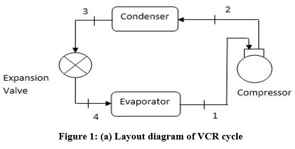
Figures 1(a) and 1(b) demonstrate the layout and related pressure vs. specific enthalpy diagram of the VCR system, respectively. Here the effect of superheating in evaporator and sub-cooling in condenser has also been considered.
 | Figure 1 (a): Layout diagram of VCR cycle
|
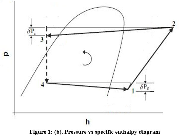 | Figure 1 (b): Pressure vs specific enthalpy diagram.
|
The ratio of heat absorbed in the evaporator to work consumed by the compressor is known as COP, that is used to assess the performance of any VCR system.

To calculate exergy destruction in diverse components of the VCR system following equation (2) – (5) have been used [19]:
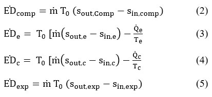
Total exergy destruction is the sum of exergy destruction in each component of the system and is represented as follows:

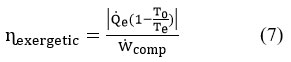
The ratio of COP of the system under consideration to COP of the system operated reversibly (Carnot COP) is known as energetic efficiency,
Exergy destruction ratio (EDR) is ratio of irreversibility associated with a component to the exergy of fuel supplied [10]:

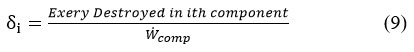
The efficiency defect (.png) is an indicator that gives the information about the fraction of energy (input) destroyed in a specific component so that one can find the component which performs worst in the system.
is an indicator that gives the information about the fraction of energy (input) destroyed in a specific component so that one can find the component which performs worst in the system.
Result and Discussion
For analysis following parameters have been taken and can be given as follows
- Capacity of System = 1TR 20.
- Temperature in evaporator = 4.5°C.
- The temperature of the condenser varies between 40°C - 60°C.
- The evaporator and condenser experience pressure drops in the range of 10 to 40 kPa.
- Isenthalpic expansion in the expansion valve.
- Compressors isentropic efficiency = 75% 10.
- Sub cooling of refrigerant at the condenser outlet = 3°C 21.
- Superheating in evaporator and suction line is of 7°C [21] and 4°C respectively.
- Dead state temperature = 25°C 10.
Following results have been obtained and are given as follows:
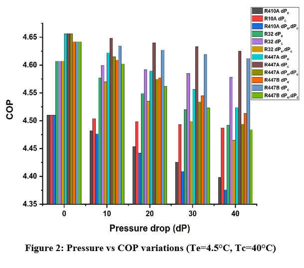
COP values correspond to pressure drop in evaporator, condenser and both in evaporator and condenser simultaneously can be seen in table 2. From figure 2 one can noticed that the change in COP is small for pressure drop in condenser, whereas significant reduction in COP has been observed with a reduction in evaporator pressure. As the pressure drop in the evaporator grows, refrigerating effect and cooling capacity both decrease and correspondingly an increment in pressure ratio across the compressor is found that increases the compressor work. In combination, both of these phenomena contribute to a decrease in COP. However maximum COP was obtained with R447A followed by R447B, R32, and R410A. With no pressure drop, R447A has 3.24% greater COP compared to R410A While the COP of the R447B and R32 systems are greater than the COP of the R410A system by 2.93% and 2.15%, respectively. As the pressure drop increases less COP has been obtained for all the studied systems. At a pressure drop of 40kpa in the evaporator and condenser, 2.48% and 0.51% drops in COP have been obtained using the R410A system. For the R32 operating system, 2.5% and 0.63% less COP is obtained compared to the no pressure drop condition. With R447A drop in COP at a pressure drop of 40kpa is 2.84% and 0.67% whereas it is 2.78%and 0.68% less COP for R447B operated system. For evaporator pressure drop of 40kpa, the COP of R32 operated system is 2.14% higher than R410A system whereas R447A and R447B operated systems have 2.86% and 2.61% higher COP than R410A operated system. With the same pressure drop of 40kpa in the condenser, R32 operated system has 2.03% higher COP than the R410A system. R447A and R447B have 3.08% and 2.79% higher COP than R410A.
Table 2: COP values considering pressure drop.
dP (kpa) | R410A | R32 | R447A | R447B | ||||||||
COP @ dPe | COP @ dPc | COP @ dPe & dPc | COP @ dPe | COP @ dPc | COP @ dPe & dPc | COP @ dPe | COP @ dPc | COP @ dPe & dPc | COP @ dPe | COP @ dPc | COP @ dPe & dPc | |
0 | 4.51 | 4.51 | 4.51 | 4.607 | 4.607 | 4.607 | 4.656 | 4.656 | 4.656 | 4.642 | 4.642 | 4.642 |
10 | 4.482 | 4.504 | 4.476 | 4.577 | 4.599 | 4.57 | 4.622 | 4.648 | 4.615 | 4.609 | 4.634 | 4.602 |
20 | 4.454 | 4.498 | 4.442 | 4.549 | 4.592 | 4.535 | 4.589 | 4.64 | 4.574 | 4.577 | 4.627 | 4.562 |
30 | 4.426 | 4.493 | 4.409 | 4.52 | 4.585 | 4.499 | 4.556 | 4.633 | 4.534 | 4.545 | 4.619 | 4.523 |
40 | 4.398 | 4.487 | 4.376 | 4.492 | 4.578 | 4.465 | 4.524 | 4.625 | 4.494 | 4.513 | 4.612 | 4.484 |
.jpg) | Figure 2: Pressure vs COP variations (Te=4.5°C, Tc=40°C).
|
Figure 3 shows total exergy destruction with respect to pressure drop. Here the variation in total exergy destruction is negligible for condenser pressure drop whereas significant reduction in total exergy destruction has been calculated with a drop in evaporator pressure. Exergy destruction in R447A operated system is minimum among the studied refrigerants. From table 3 the pressure drop increases, total exergy destruction also increases and it is more when pressure loss in the evaporator takes place and considerably less with condenser pressure drop. Here total exergy destruction is the least in R447A operating system but the percentage drop in TED is highest in R447A compared to other studied refrigerants. At a pressure of 40kpa in the evaporator, R410A operated system has 2.8% more exergy destruction compared to the no pressure loss condition whereas R447A and R447B have 3.32% and 3.14% more exergy destruction respectively. Pressure drop in the condenser is not significant and has very less increment in total exergy destruction. With the consideration of a pressure drop of 40kpa, both in evaporator and condenser, total exergy destruction is calculated as 4.08% higher in R447A operated system and is least in R410A. R447B and R32 have 3.9% and 3.47% higher exergy destruction respectively compared to no pressure drop condition.
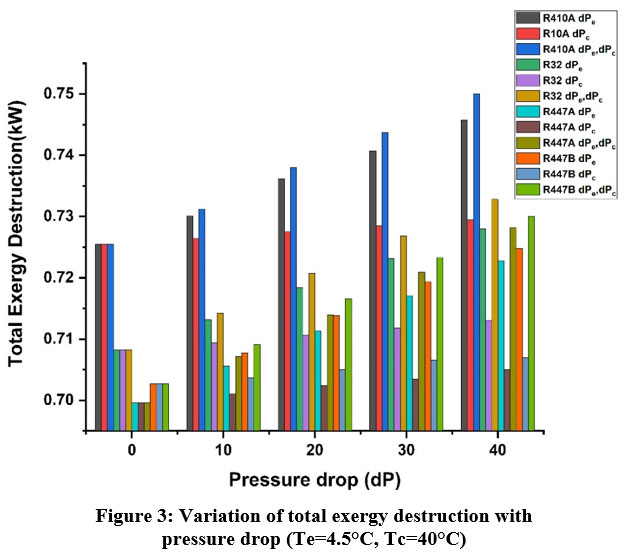 | Figure 3: Variation of total exergy destruction with pressure drop (Te=4.5°C, Tc=40°C).
|
Table 3: Total Exergy destruction calculation with consideration of pressure drop.
| 410A | 32 | 447A | 447B | ||||||||
dP (kpa) | TED @ dPe | TED @ dPc | TED @ dPe & dPc | TED @ dPe | TED @ dPc | TED @ dPe & dPc | TED @ dPe | TED @ dPc | TED @ dPe & dPc | TED @ dPe | TED @ dPc | TED @ dPe & dPc |
0 | 0.725 | 0.725 | 0.725 | 0.708 | 0.708 | 0.708 | 0.700 | 0.700 | 0.700 | 0.703 | 0.703 | 0.703 |
10 | 0.730 | 0.726 | 0.731 | 0.713 | 0.709 | 0.714 | 0.706 | 0.701 | 0.707 | 0.708 | 0.704 | 0.709 |
20 | 0.736 | 0.728 | 0.738 | 0.718 | 0.711 | 0.721 | 0.711 | 0.702 | 0.714 | 0.714 | 0.705 | 0.717 |
30 | 0.741 | 0.729 | 0.744 | 0.723 | 0.712 | 0.727 | 0.717 | 0.704 | 0.721 | 0.719 | 0.707 | 0.723 |
40 | 0.746 | 0.729 | 0.750 | 0.728 | 0.713 | 0.733 | 0.723 | 0.705 | 0.728 | 0.725 | 0.707 | 0.730 |
Figures 4 and figure 5 shows variation of exergetic efficiency and EDR with the pressure loss in evaporator and condenser respectively. From figures it is seen that exergy efficiency decreases as pressure drop increases and it is highest with R447A, then R447B, R32, and R410A. It is also seen that EDR is increasing with drop in pressure and is maximum with R410A followed by R32, R447B, and R447A. Here large variation in EDR is calculated with drop in evaporator pressure and the same can be depicted from table 4 and table 5.
Table 4: Exergy destruction ratio and exergetic efficiency with consideration of pressure drop in evaporator.
dPe (kpa) | R410A | R32 | R447A | R447B | ||||
?Exergetic | EDR | ?Exergetic | EDR | ?Exergetic | EDR | ?Exergetic | EDR | |
0 | 0.333 | 2.000 | 0.340 | 1.938 | 0.344 | 1.908 | 0.343 | 1.915 |
10 | 0.331 | 2.020 | 0.338 | 1.957 | 0.342 | 1.927 | 0.340 | 1.939 |
20 | 0.329 | 2.038 | 0.336 | 1.977 | 0.339 | 1.950 | 0.338 | 1.959 |
30 | 0.327 | 2.058 | 0.334 | 1.996 | 0.337 | 1.970 | 0.336 | 1.978 |
40 | 0.325 | 2.078 | 0.332 | 2.012 | 0.334 | 1.993 | 0.333 | 2.001 |
Table 5: Exergy destruction ratio and exergetic efficiency with consideration of pressure drop in condenser.
dPc (kpa) | R410A | R32 | R447A | R447B | ||||
?Exergetic | EDR | ?Exergetic | EDR | ?Exergetic | EDR | ?Exergetic | EDR | |
0 | 0.333 | 2.000 | 0.340 | 1.938 | 0.344 | 1.908 | 0.343 | 1.915 |
10 | 0.333 | 2.004 | 0.340 | 1.942 | 0.343 | 1.911 | 0.342 | 1.920 |
20 | 0.332 | 2.008 | 0.339 | 1.946 | 0.343 | 1.915 | 0.342 | 1.927 |
30 | 0.332 | 2.012 | 0.339 | 1.954 | 0.342 | 1.924 | 0.341 | 1.930 |
40 | 0.332 | 2.016 | 0.338 | 1.958 | 0.342 | 1.927 | 0.341 | 1.935 |
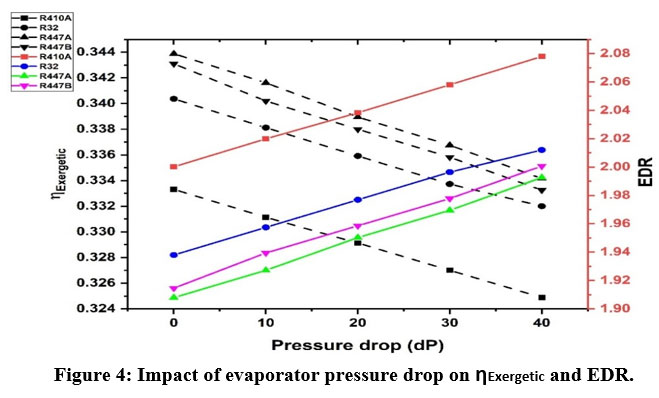 | Figure 4: Impact of evaporator pressure drop on ?Exergetic and EDR.
|
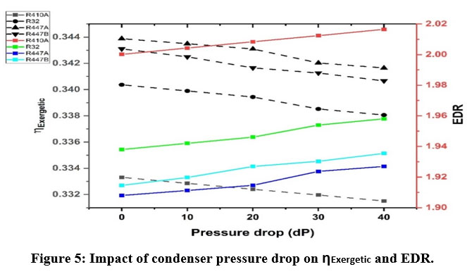 | Figure 5: Impact of condenser pressure drop on ?Exergetic and EDR.
|
With increase in pressure drop in evaporator, percentage drop in exergy efficiency and exergy destruction ratio is highest in R447B that is 2.87% and 4.5% respectively (at dP=40kpa). For R447A at same pressure drop condition exergy efficiency has been calculated as 2.83% lower and EDR is 4.44% lower than the condition of no pressure drop. R32 operated system has 2.46% less exergy efficiency along with 3.82% less EDR compared to no pressure drop situation. With pressure drop in condenser, percentage drop in exergy efficiency is in the range of 0.11% to 0.71% that is insignificant. Similarly percentage drop in EDR, considering all the refrigerants is in the range of 0.17% to 1.09% only.
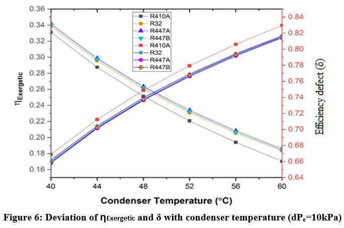
The variation in efficiency defect and exergy efficiency with condenser temperature is shown in Figure 6. Here R410A has the lowest exergy efficiency of the refrigerants investigated, and so has the highest efficiency defect. The efficiency defect for all refrigerants rises, as the condenser temperature increase, and corrosponding exergy efficiency falls. R447A has the least efficiency defects and the highest exergy efficiency.
 | Figure 6: Deviation of ?Exergetic and ? with condenser temperature (dPe=10kPa).
|
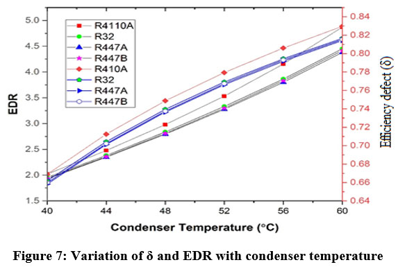
The fluctuation of efficiency defect and EDR with respect to condenser temperature is shown in Figure 7. EDR increases dramatically with condenser temperature and reaches a maximum for R410A. Fluctuations in EDR are smaller when the condenser temperature is 40°C, but when it reaches 60°C, substantial variations in EDR are recorded. The impact of pressure decrease on exergetic efficiency and total exergy destruction is depicted in Figure 8. Here total exergy destruction is greatest when pressure drops simultaneously in both the evaporator and the condenser. However, large decline in the evaporator pressure has an adverse impact on overall destruction of exergy. Among the refrigerants studied, R447 had the least overall exergy destruction and the highest exergy efficiency.
 | Figure 7: Variation of ? and EDR with condenser temperature (dPe=10kPa).
|
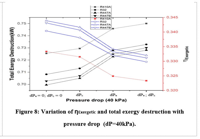 | Figure 8: Variation of ?Exergetic and total exergy destruction with pressure drop (dP=40kPa).
|
Conclusions
The following conclusions were drawn and can be given as:
The change in COP is small for condenser pressure drop, whereas significant reduction in COP has been observed with evaporator pressure. As the pressure loss in evaporator grows, refrigerating effect and cooling capacity both decrease, causes increment in pressure ratio across the compressor and leads to increase in compressor work. In combination, both of these phenomena contribute to a decrease in COP.
Variation in total exergy destruction is negligible for condenser pressure drop whereas significant reduction in total exergy destruction has been calculated with a drop in evaporator pressure. Although total exergy destruction in R447A operated system is minimum among the studied refrigerants.
Exergy efficiency decreases as pressure drop increases both in evaporator and condenser but exergy efficiency is very sensitive to pressure drop in evaporator and decreases at much faster rate. In the analysis exergy efficiency is found to be maximum with R447A, then R447B, R32, and R410A.
With increase in condenser temperature, the efficiency defect for all refrigerants rises, and exergy efficiency falls. Drastic fall in exergy efficiency has been calculated with increase in condenser temperature. Among the studied refrigerants, R447A has the least efficiency defects and correspondingly highest exergy efficiency.
Exergy efficiency changes dramatically as condenser temperatures rise. Exergy efficiency decreased by roughly 45% as the temperature of the condenser rises from 40°C to 60°C.
Considering the findings of the investigation, R447A is the best option that can be considered as replace of R410A since it has the highest exergy efficiency as well as the highest COP at various condenser temperatures. R447A has the least total exergy destruction among the studied refrigerants. It may also be concluded that performance of the system is adversely affected when pressure drop takes place particularly in the evaporator so extra care must be taken.
Future Scope
Experimental analysis can be performed on air conditioning system with consideration of pressure drop in suction line as well as in delivery line and can be used for standardising the model to improve system simulation. With these calibrated model, the impact on COP, exergy efficiency and efficiency defect can be evaluated and validation could be made.
Conflict of Interest
There is no conflict of Interest.
Funding Sources
There is no funding Source.
References
- J. U. Ahamed, R. Saidur, and H. H. Masjuki, “A review on exergy analysis of vapor compression refrigeration system,” Renew. Sustain. Energy Rev., vol. 15, pp. 1593–1600, Apr. 2011, doi: 10.1016/j.rser.2010.11.039.
CrossRef - B. O. Bolaji and Z. Huan, “Ozone depletion and global warming: Case for the use of natural refrigerant – a review,” Renew. Sustain. Energy Rev., vol. 18, pp. 49–54, 2013, doi: https://doi.org/10.1016/j.rser.2012.10.008.
CrossRef - Q. Yuan, Y. Ma, C. Liu, B. Dai, and Q. Yan, “Thermodynamic perfectibility based analysis of energy-efficiency standards for air conditioning products in China,” Energy Build., vol. 43, no. 12, pp. 3627–3634, 2011, doi: https://doi.org/10.1016/j.enbuild.2011.09.035.
CrossRef - K. D. Patel TM, Patel AM, “Global Climate Change Impacts in the World.,” Curr World Env., vol. 6, pp. 217–223, 2011.
CrossRef - A. K. Vuppaladadiyam et al., “Progress in the development and use of refrigerants and unintended environmental consequences,” Sci. Total Environ., vol. 823, p. 153670, 2022, doi: https://doi.org/10.1016/j.scitotenv.2022.153670.
CrossRef - W. Chen, “A comparative study on the performance and environmental characteristics of R410A and R22 residential air conditioners,” Appl. Therm. Eng., vol. 28, no. 1, pp. 1–7, 2008, doi: https://doi.org/10.1016/j.applthermaleng.2007.07.018.
CrossRef - R. Saidur, H. H. Masjuki, and M. Y. Jamaluddin, “An application of energy and exergy analysis in residential sector of Malaysia,” Energy Policy, vol. 35, pp. 1050–1063, Feb. 2007, doi: 10.1016/j.enpol.2006.02.006.
CrossRef - K. S. HMOOD, V. APOSTOL, P. O. P. Horatiu, V. BADESCU, and P. O. P. Elena, “Drop-in and retrofit refrigerants as replacement possibilities of R134a in domestic/commercial refrigeration and automobile air conditioner applications,” J. Therm. Eng., vol. 7, no. 7, pp. 1815–1835, 2021.
CrossRef - A. Lateef Tarish, M. Talib Hamzah, and W. Assad Jwad, “Thermal and exergy analysis of optimal performance and refrigerant for an air conditioner split unit under different Iraq climatic conditions,” Therm. Sci. Eng. Prog., vol. 19, p. 100595, 2020, doi: https://doi.org/10.1016/j.tsep.2020.100595.
CrossRef - A. Arora and S. C. Kaushik, “Theoretical analysis of a vapour compression refrigeration system with R502, R404A and R507A,” Int. J. Refrig., vol. 31, no. 6, pp. 998–1005, 2008, doi: https://doi.org/10.1016/j.ijrefrig.2007.12.015.
CrossRef - C. Sunardi, Markus, and A. Setyawan, “The effects of the condenser pressure drop on the cooling performance of an air conditioning unit using R-410A,” AIP Conf. Proc., vol. 2001, no. 1, p. 20006, Aug. 2018, doi: 10.1063/1.5049966.
CrossRef - Z. Li, H. Jiang, X. Chen, and K. Liang, “Evaporation heat transfer and pressure drop of low-gwp refrigerants in a horizontal tube,” Int. J. Heat Mass Transf., vol. 148, p. 119150, Feb. 2020, doi: 10.1016/J.IJHEATMASSTRANSFER.2019.119150.
CrossRef - J. Zhang et al., “R410A flow boiling in horizontal annular channels of enhanced tubes, part I: Pressure drop,” Int. J. Refrig., vol. 137, pp. 70–79, 2022, doi: https://doi.org/10.1016/j.ijrefrig.2022.02.009.
CrossRef - C. Subei and G. Schmitz, “Analysis of refrigerant pipe pressure drop of a CO2 air conditioning unit for vehicles,” Int. J. Refrig., vol. 106, pp. 583–591, 2019, doi: https://doi.org/10.1016/j.ijrefrig.2019.04.005.
CrossRef - Z. Qi, “Quick and empirical correlations for refrigerant pressure drop in mobile air conditioning system evaporators,” Int. J. Refrig., vol. 55, pp. 30–36, 2015, doi: https://doi.org/10.1016/j.ijrefrig.2015.03.009.
CrossRef - S. Du et al., “Investigation on heat transfer and pressure drop correlations of R600a air-cooled finned tube evaporator for fridge,” Int. J. Refrig., Jul. 2022, doi: 10.1016/J.IJREFRIG.2022.07.012.
CrossRef - M. Khairul Bashar, K. Nakamura, K. Kariya, and A. Miyara, “Development of a correlation for pressure drop of two-phase flow inside horizontal small diameter smooth and microfin tubes,” Int. J. Refrig., vol. 119, pp. 80–91, 2020, doi: https://doi.org/10.1016/j.ijrefrig.2020.08.013.
CrossRef - A. M. B. Medina, “REGULATION (EU) N0. 517/2014 OF THE EUROPEAN PARLIAMENT AND OF THE COUNCIL April 16, 2014 on fluorinated greenhouse gases and Regulation (EC) No. 842/2006,” Actual. Jurídica Ambient., vol. L 150/195, no. 37, pp. 46–46, 2014.
- K. M. Dincer I., “Refrigeration Systems and Applications, Second Edition, John Willey and sons limited.,” 2010.
- K. A. Joudi and Q. R. Al-Amir, “Experimental Assessment of residential split type air-conditioning systems using alternative refrigerants to R-22 at high ambient temperatures,” Energy Convers. Manag., vol. 86, pp. 496–506, 2014, doi: https://doi.org/10.1016/j.enconman.2014.05.036.
CrossRef - A. G. Devecio?lu and V. Oruç, “An analysis on the comparison of low-GWP refrigerants to alternatively use in mobile air-conditioning systems,” Therm. Sci. Eng. Prog., vol. 1, pp. 1–5, 2017, doi: https://doi.org/10.1016/j.tsep.2017.02.002.
CrossRef


