GTL Technology for Production of Clean Fuels
Merajuddin Ahmad1 *
1
Applied Science Section,
University Polytechnic,
Aligarh Muslim University,
Aligarh,
202 002
U.P.
India
http://dx.doi.org/10.12944/CWE.1.1.02
There is a world-wide demand for clean, reliable and affordable energy. New technologies are needed to produce more oil and natural gas from ‘stranded’ locations. This work is based on gas to liquid (GTL) conversion of natural gas through Fischer-Tropsch (FT) synthesis. Fe & Co based catalysts of varying compositions were prepared in the laboratory and its performance was checked for the FT reaction. CO & H2 (from natural gas source) were mixed in the desired proportion and allowed to pass through the catalyst bed for synthesis of complex hydrocarbons, which was then condensed to yield liquid products viz. diesel,kerosene, gasoline etc. The resultant product is free of SOx and NOx and is environmental-friendly. Also, it has good fuel characteristics, which signifies the importance of GTL technology in future.
Copy the following to cite this article:
Ahmad M. GTL Technology for Production of Clean Fuels. Curr World Environ 2006;1(1):07-10 DOI:http://dx.doi.org/10.12944/CWE.1.1.02
Copy the following to cite this URL:
Ahmad M. GTL Technology for Production of Clean Fuels. Curr World Environ 2006;1(1):07-10. Available from: http://www.cwejournal.org/?p=503
Download article (pdf)
Citation Manager
Publish History
Introduction
GTL is the use of natural gas1 to make a clean versatile liquid fuel. Natural gas is available in large quantities and the reserve is not used to the same extent as petroleum crude. There are many potentially rich gas fields that are not drilled (about 2500tcf of natural gas, nearly half of proven reserve is left in the ground) because of the need to lay expensive pipes to transport the gas. Transporting by ship, train or truck is much less costly, but methane’s high volume as a gas prevents it from being transported in bulk. GTL technology has the potential to utilize natural gas or any other resource rich in methane i.e., coal-bed methane, biogas from waste and effluent anaerobic treatment, gas hydrates and refinery gas.7-12 The additional advantage is that existing diesel engines can use GTL fuels without modification, which is a drawback for alternative fuels like CNG and LNG.2 GTL diesel, in particular, is ultra clean, sulfur free with a very high typical refinery diesel range of 45-50. Due to clean qualities, GTL fuels are excellent feedstock for fuel cells.6 Although, liquid natural gas (LNG) is one way of accomplishing this, the need to constantly keep LNG at a very low temperature is a drawback, sometimes a serious one. This leads to the other area of GTL, in which natural gas is converted into liquids useful as fuels and chemicals feedstock through Fischer-Tropsch Synthesis (FTS). The process consists essentially of two steps.3-5
Step-1
Syngas generation: Steam reforming of Natural gas leads to conversion of methane to a mixture of hydrogen and carbon monoxide.
2CH4 + O2 = 2CO + 4H2
Step-2
Syngas Conversion:Conversion of CO+H2 mixture into the desired products through FT Synthesis.
 |
Figure - 1: Fe catalyst (GHSV = 500/h) Click kere to view figure |
Experimental
The experimental program was to convert the syngas of specific ratio into middle distillates viz. diesel, gasoline, kerosene etc. using suitable catalysts at varying reaction conditions (temperature, pressure and space velocity). Two different catalyst (one iron based and one cobalt based) was prepared and experimental runs for each were performed.
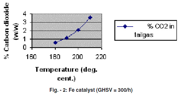 |
Figure - 2: Fe catalyst (GHSV = 300/h) Click kere to view figure |
Process Description
Experiments were carried out in a 100ml Fixed Bed Reactor(FBR). The reactor was equipped with a preheater, temperature control device and dynablander gas mixing mass controllers. A CO2 analyzer was connected to the outlet line. Dynablander was connected to the preheater for controlling the flow of carbon monoxide and hydrogen. On-line connection of the tail gas was done to Gas Chromatograph (Chemito,GC 1000) for analysis of the gases coming out of the reactor.
Table -1: ASTM distillation* report of this sample
| S No. | % Volume of distillate | True Boiling Point, oC |
| 1 | IBP | 117 |
| 2 | 30 | 176 |
| 3 | 50 | 195.5 |
| 4 | 80 | 277 |
| 5 | 90 | 343.5 |
| 6 | FBP | 416 |
*Analysis done at IIP, Dehradun
The work on the conversion of syngas to liquid hydrocarbons was initiated with iron catalyst. 30cc of the prepared Fe catalyst was charged in the reactor. Reduction of the catalyst with hydrogen gas was done before the start of synthesis run. (First 4 hours-150oC, Next 4 hours-250oC, GHSV -1500h-1).
After reduction, synthesis run of the syngas (CO + H2 mixture) was performed. (Catalyst volume = 34cc, Temperature= 220oC-180oC, Pressure = 20kg/cm2, GHSV = 600h-1-300 h-1, H2 +CO ratio=1.75). CO and H2 were fed from the cylinders and after mixing them in the desired proportion through the mass flow control meters, it was fed to the preheater. Preheating of the gas was done at around 150oC and then it was fed to the reactor. The synthesis run was performed for almost 110hrs by varying the reaction conditions (temperature, pressure, space velocity) from time to time. GC analysis of the tail gas was done at regular intervals.
Next, the experiment was performed using cobalt catalyst. First reduction of the catalyst was done for 50 hrs using hydrogen gas. (First 10 hours= 325oC, Next 40 hours= 450oC, GHSV = 1500h-1). After it, the synthesis run was performed. (Catalyst volume-30cc, Temperature=200 oC-240oC, Pressure= 25kg/cm2, GHSV=500 h-1-300h-1, H2 +CO ratio=2.0). The reaction was performed for almost 100 hrs at different temperatures for a certain duration. The liquid hydrocarbon collected was then distilled. The GC and distillation results are discussed as follows.
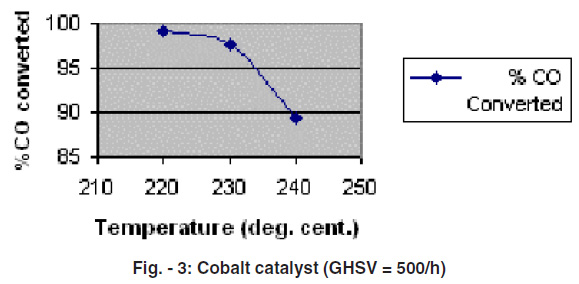 |
Figure - 3: Cobalt catalyst (GHSV = 500/h) Click kere to view figure |
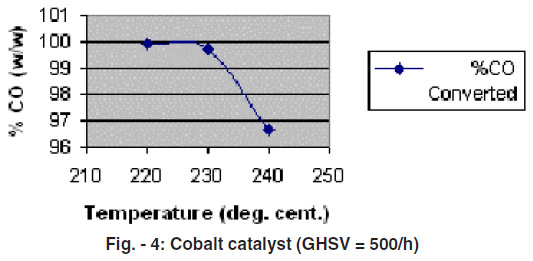 |
Figure - 4: Cobalt catalyst (GHSV = 500/h) Click kere to view figure |
Results and Discussion
Iron Catalyst
Analysis of the tail gas by GC showed the %CO present in it. The result of the %CO converted with respect to temperature is shown in Fig. -1. It is observed that at space velocity 500h-1, pressure 20 kg/cm2 and for H2/CO ratio1.75, the favorable temperature for the reaction seems to be 210oC. At this temperature, much of the carbon monoxide is being converted to products and the reaction is being favored. Further reduction of temperature to 200oC leads to lower conversion of CO.
Next the gas hourly space velocity(GHSV) was reduced to 300h-1 keeping the other parameters constant and the reaction was carried out at varying temperatures from180oC-210oC.
The result is plotted in Fig. -2. It is again observed that the conversion is more at 210oC.
Cobalt Catalyst
Synthesis run at two different GHSV (500 h-1 & 1000 h-1) was performed for cobalt catalyst (30cc). The results are plotted in Fig. 3 & 4 respectively. As it can be seen from the plots that the optimum temperature for both space velocities (at pressure = 25kg/cm2, H2/CO =2.05) seem to be around 220oC for the cobalt catalyst.
The liquid product collected from run 2 using cobalt catalyst was distilled. The ASTM distillation* report of this sample is given in
Table -1.
From the table it can be seen that the yield of middle distillates (TBP=176-343oC) is 60%, which is very encouraging.
Conclusion
In the present investigation, an effort has been made to study the activities of iron and cobalt catalysts for the conversion of syngas to liquid hydrocarbons. From the work carried out, the following conclusions are made:
- The variables that influence the reaction are – temperature, pressure, feed H2/CO ratio, gas hourly space velocity etc.
- Since the reaction is exothermic, there is an optimum temperature for maximum selectivity for each of the fractions. FT synthesis is favored in the temperature range of 180oC-210oC for fixed bed reactor study.
- Theoraticaly, low H2/CO ratio will increase the selectivity for olefins, higher molecular weight hydrocarbons and increase carbon deposition, whereas high H2/CO ratio will increase the selectivity for products having higher H/C ratio viz., lower alkanes particularly methane. In this study H2/CO ratio varied between 1.75-2.05.
- With the reduction in space velocity, the conversion increases for iron catalyst.
- Of the two catalyst tested (iron & cobalt), the conversion as well as yield of the desired product was greater for cobalt catalyst.
- Use of diluent has the advantage of easily taking out the heat but has the disadvantage that it may decrease yield/unit volume of feed. In order to check the effect of other variables, influence of diluents (nitrogen) was kept at the minimum.
References
- Wilhelm- Fischer, D.J. Tropsch: A futuristic view, Fuel processing Technology, (2001) 71: 139-155.
- Tindall, B., Crews, A., Gas to Liquids Processing; Bringing clean fuels to market, March (1998) 18-20.
- Espinoza, R.L., Steynberg, A.P., Jager, B., Vosloo, A.C., Applied catalysis, A (1999) 186: 13-26, 41-54.
- Dry, M.E., Anderson, J., Boudard, M.,(Eds), The Fischer-Tropsch Process, Catalysis, Science & Technology, (1981) 1: 319-343.
- Dry, Applied Catalysis, (2002) 71: 227-241.
- Samuel, P., GTL Technology-Challenges & Opportunities in Catalysis, Bulletin of the Catalysis society of India, (2003) 2: 82-99.
- Sault, AG, Datye AK, Journal of Catalysis 140, 136-149
- Rapport, I.B., Chemistry & Technology of Synthetic Liquid Fuels, Chp. 20: 282-309
- Emmett, P.H.- Catalysis Vol.I, Fundamental Principles ( Part I), Chp.7
- Chadwick D, Vg K.L., Chemical Engineering Science (1999) 54: 3587-3592.
- Irving Wender- Reactions of Synthesis gas, Fuel Processing Technology, (1996) 48: 189-297.
- Henry H. Storch, Robert B. Anderson, The Fischer & Related Synthesis, 1-35