Strengthening of Steel Shear Wall by Glass Fiber Reinforced Polymer
Taleb Heidary1 and Mohamadreza Habibi1 *
http://dx.doi.org/10.12944/CWE.10.Special-Issue1.52
Steel shear wall (SSW) is a new seismic system, which had proper performance against lateral loads during past earthquakes and numerical and experimental studies. Although plate buckling in elastic zone provides post buckling behavior but it causes the reduction of energy absorption, that strengthening with polymer fiber has been proposed as a new method in recent years. In this paper, the performance of steel shear walls with glass fiber reinforced polymers (GFRP) is evaluated and some models will be analyzed using ANSYS software in nonlinear analysis. The results show that the polymer cover increases stiffness, shear capacity and energy absorption but decrease ductility slightly. In investigation of fiber polymer orientation, the study results show that at the angle of 60 degrees, energy absorption increase slightly and decrease about 15 percent at 90 degrees and will change as a function of steel material and span length at 30 and 45 degrees.
Copy the following to cite this article:
Heidary T, Habibi M. Strengthening of Steel Shear Wall by Glass Fiber Reinforced Polymer. Special Issue of Curr World Environ 2015;10(Special Issue May 2015). DOI:http://dx.doi.org/10.12944/CWE.10.Special-Issue1.52
Copy the following to cite this URL:
Heidary T, Habibi M. Strengthening of Steel Shear Wall by Glass Fiber Reinforced Polymer. Special Issue of Curr World Environ 2015;10(Special Issue May 2015). Available from: http://www.cwejournal.org/?p=10980
Download article (pdf) Citation Manager Publish History
Introduction
In recent years, due to urban development and growth of construction, with attention to the issue of earthquake, many seismic systems with their own feature are used to control the lateral loads. Selection of resisting system against lateral loads depends on combination of loading, the structure behavior, conduction of gravity loads, geographic area, construction method, structure geometry, limitation of regulations, maximum displacement and etc. Many structural systems has been proposed and applied as yet for example moment frame system, different types of braced systems, shear wall (including concrete, steel and composite), active and passive control systems using dampers, or resisting systems in unaided masonry buildings. Stiffness, strength, ductility, energy absorption and system proper behavior, during an earthquake are among the most important parameters to select a structural seismic system. Researchers are always looking for the ideal system to resist lateral loads, in addition to having high stiffness and strength; it also has high ductility and energy dissipation.
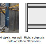
Steal Shear Wall is one of the lateral load resisting systems that recently attracted the attention of many researchers and engineers. This system is consist of vertical steel plate infill connected to the surrounding beams and columns, and installed one or more bays along the full height of the structure to form a cantilevered wall (Figure 1). This system is used in steel buildings about four decades ago, because of high stiffness and ductility, suitable energy dissipation, the speed of construction and structural lose weight compared to other systems and the trend of using is growing. Their use, compared with the moment frames, has about 50% saving in steel at buildings (Astaneh-Asl, 2001).
 |
|
Steel plate shear walls are executively simple, and there is no particular complexity in the system, thus engineers, technicians and technical workers with their technical knowledge and without having to learn new skills can perform the system. Work precision is at the level of conventional precision in steel structures and with that consideration, there will result much higher executive safety factor compared with the other systems. Due to its simplicity and the possibility of constitution in a factory and installed on the site, system executive speed is high and the enforcement costs will be reduced significantly. In the steel plate shear wall system, because of the expansion of materials and connections, tension modification is much better than other seismic systems like frames and braces which usually their materials are classified and connections are concentrated, and system behavior is more appropriate especially at the plastic zone.
Structures Built Using Steel Plate Shear Wall and Studies in This Field
Academic and laboratory research on steel plate shear wall system began at the seventies and the system was used in important buildings in some developed countries. At first, in 1970, steel shear walls were used in Japan in new buildings and they were used for seismic improvements to existing buildings in the United States (Astaneh-Asl, 2001). In some cases the steel shear walls were covered with concrete to form a kind of composite shear wall. The important buildings that have been done with steel shear walls and the studies in this case include:
Japan
Nippon (1970), 20-storey office building and Shinjuku Nomura, 51-storey High-rise building in Tokyo and City Hall 35-story tower in Kobe are built using steel shear wall (Astaneh-Asl, 2001). In 1973, Takanashi performed the first major research on one-floor steel shear wall. The results of the experiments indicate that the samples had ductile behavior. The test results were in good agreement with the Von-Mises yielding criterion in pure shear. He also performed experiments on two samples of two-story steel shear walls and the results of the experiment were used in the design of a tower in Japan. In these cases the test results were very close to the results of Von-Mises theory formulas. The researchers concluded that rules and the theory formulas of plate girder can be used to obtain stiffness and strength of steel shear walls (Takanashi et al., 1973). Turi et al in Japan in 1996 studied steel shear wall performance with "Low-yield-point Steel" to use it in building of some towers in Japan. The results of this research were used in design and construction of Yamaguchi (1998) tower (Torii et al., 1996), (Yamaguchi et al., 1998).
United States
Hyatt Regency 30-story in Dallas, Texas, Sylmar 6-story hospital in Los Angeles- California, The Century 52-story residential building in San Francisco-California, Federal courthouse 23-story in Seattle-Washington, Strengthening Oregon state library concrete building, health care building in Charleston, H.C.Moffit 16-story hospital, are among buildings which used steel shear wall in their construction(Astaneh-Asl, 2001). Elgaaly and Caccese in 1993 conducted wide tests under monotonic and cyclic loading. They declared that if a relatively thick steel plate be used in construction of the wall, system resistance will relate to system instability, caused by buckling of the respective column and system resistance will not change much by increasing the thickness of the steel(Elgaaly et al., 1993). In 1998-2022 professor Astaneh-Asl and Zhao at Berkeley University, studied seismic behavior of steel and composite shear wall under cyclic loading in a series of laboratory investigations and proposed the design coefficients(Astaneh-Asl, 2001). Behbahanifard in 2003 performed numerical and experimental studies on the three floors model that the upper flange of first floor beam was with failure. Specimen showed high elastic stiffness, ductility, energy dissipation capability and hysteresis loop stability. In the numerical modeling, it was proved that the plate primary defect has an important impact on the stiffness of the shear panel but has a negligible impact on the shear capacity. He fined that increasing of gravity loads decreases the stiffness, overturning moment, shear capacity and ductility (Rezai et al., 1999), (Behbahanifard et al., 2003).
Canada
In construction of ING, Canam Manac Group buildings in Quebec and 25-story building in Edmonton, the steel shear wall resisting system is used. Timler and Kulak in 19883 did some tests on a two story steel shear wall specimens without stiffeners (Timler, P. A et al., 1983). The results showed high ductility and strength of this system and at the same year Thorbun et al based on this test results, suggested an equation for determine the angle of tensile field inclination and controlled the precision with some experiments(Timler, P. A et al., 1983). Driver et al in 1996 and 1998 tested a 4-storey steel shear wall specimen under cyclic loads. Although specimen rupture was not because of yielding steel plate and actually happened because of stress concentration at the column foot, but hysteresis response curves of the wall implies extra resistance coefficient about 1.3 and ductility coefficient more than 6 (Driver RG et al., 1998).
Europe
Among the buildings that have been built with this system, Byer-Hochhaus 32-story building in Leverkusen, Germany can be mentioned. Also in 1992, researchers like Sabouri-Ghomi and Roberts from Britain studied the built up steel shear wall with or without openings. The other interesting result from these experiment series is investigating the effect of opening on stiffness and strength of the shear wall (Sabouri-Ghomi et al., 1992).
Also in the years 2001-2012 the Iranian researchers of Amirkabir University did numerical and experimental investigation of the steel and composite shear wall behavior. In this research, a new system of composite shear walls with carbon fiber reinforced polymers have been wide numerically and experimentally studied and the behavior of steel shear wall composited with a reinforced concrete layer and fiber polymers were investigated with 224 numerical models. In addition, a new system of steel plate shear wall with dubbed plates was introduced and overviewed (Hatami et al., 2005).
Fiber Reinforced Polymers
Among the innovations and techniques in structural strengthening, FRP (Fiber Reinforced Polymers/Plastics) have a special role, as far as the opinion of some experts, FRP should be called the Third Millennium Construction Materials. In addition to the use of these materials in strengthening concrete structures, using them in strengthening steel structures have been proposed in the past decade, seriously. Polymer composite plates are materials that formed from two separate parts: Polymer fibers and resin. The ultimate strength of polymer fibers along their length is too high and they include: Carbon, Glass and Kevlar. Resin is fibers holder and transports load and prevent crack in the structure. Resin is usually made of epoxy, polyester, etc. Collection of fibers and resin make a plate which called Lamina (Jones , 1999).
Using techniques of these composites as external reinforcement due to its unique characteristics like high strength compared to weight, lightness (about 20% of steel), high chemical resistance against corrosion compared to steel and concrete, insulation of electric and magnetic fields, ease of transport and storage, non-interference and inconvenience to using the structure in perform, has found particular attention, and has opened a new window in front of engineers. On the other hand, these techniques have found a special attraction because of rapid implementation and low costs. These properties can be effective in improve the composited steel shear wall characteristics such as strength, stiffness, ductility and energy absorption. To investigate these cases a numerical study has been done by ANSYS finite element software which it will be discussed in more detail.
Modeling with the software
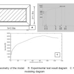
In this paper, in order to analyze the samples in nonlinear method, ANSYS finite element software is used, and in order to trust the modeling accuracy of steel shear wall composited with fiber polymers, the results of an experimental test which its geometry in Figure 2, is modeled and analyzed by the software. This is the profile of beam and column: 2IPE200+2PL150*12
The test was conducted at AmirKabir University and it is from the investigations series of composited steel shear wall behavior conducted by Farzad Hatami (Hatami et al., 2005).
 |
|
Comparison of load-displacement diagram shows the high accuracy of the modeling. Then there is the model with actual dimensions and with different fibers orientations.
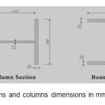
Samples Introduction; After checking the accuracy of the modeling results of finite element analysis, 2 steel shear wall samples and 12 shear wall reinforced with glass fiber polymer (with two millimeters thickness), have modeled with different orientations and analyzed in non-linear method. There are sample specifications in Table 1. In all models the steel plate thickness is 7 mm. Sample beams and columns specification in terms of mm are observable in figure 3.
 |
|
Table1: Geometric properties of steel shear wall modeled specimens
|
Specimens |
Height (m) |
Width(m) |
Orientation (degree) |
|
Ssw-s-3x5 |
3 |
5 |
----- |
|
Ssw-s-3x6 |
3 |
6 |
----- |
|
Cs-3x5-xy |
3 |
5 |
Both sides |
|
Cs-3x5-y |
3 |
5 |
90 |
|
Cs-3x5-x |
3 |
5 |
0 |
|
Cs-3x5-30 |
3 |
5 |
30 |
|
Cs-3x5-45 |
3 |
5 |
45 |
|
Cs-3x5-60 |
3 |
5 |
60 |
|
Cs-3x6-xy |
3 |
6 |
Both sides |
|
Cs-3x6-y |
3 |
6 |
90 |
|
Cs-3x6-x |
3 |
6 |
0 |
|
Cs-3x6-30 |
3 |
6 |
30 |
|
Cs-3x6-45 |
3 |
6 |
45 |
|
Cs-3x6-60 |
3 |
6 |
60 |
Analyze the Modeling Results
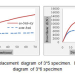
Comparison of shear walls and the reinforced ones: To compare the behavior of steel shear walls with the reinforced ones, we modeled and analyzed two shear walls with usual steel. Then we attached the polymer fiber covers to both sides of the steel plates and analyzed them. Load displacement diagrams of steel shear walls compared with the reinforced ones with glass fiber polymer covers in both sides with 2-mm thickness, is shown in figure 4. Valuable information can be inference from these figures.
 |
|
With investigation of these diagrams, it is noticed that, if there is no lateral displacement limit, capacity of reinforced shear wall will rise but steel shear walls behave in complete elasto-plastic way. In diagram figures 5 to 8 seismic parameters of the samples is drawn in bar graph and steel shear wall parameters are compared with the GFRP (2 mm thickness) reinforced ones.
 |
|
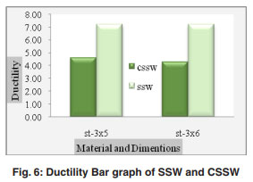 |
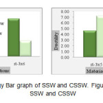
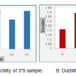
Figure 6: Ductility Bar graph of SSW and CSSW click here to view figure |
 |
|
Comparison of the graphs shows that the ductility of reinforced steel shear walls (with almost equal ratio for all samples) is always less than the ones without reinforcement. The glass polymer covers increase stiffness, shear capacity and energy absorption. The glass polymer cover increase shear capacity of samples but the impact of polymer covers on increasing shear capacity with usual steel is more than the system with mild steel. The polymer cover has a little effect on resistance coefficient of reinforced steel shear wall. Samples stiffness would increase by the polymer cover but this increment is affected by span length, in other words, with span increasing its ascending rate would be higher.
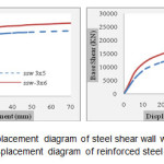
Investigation of span length on samples behavior: With increasing of the panel span, the panel slenderness increases. Behavior of steel shear wall and the reinforced ones is also influenced by the slenderness ratio. The load-displacement diagrams of steel shear wall with different spans are drawn in Figure 9. The changes of stiffness, energy absorption and etc can be observed from these diagrams. For numerical comparing of seismic parameter changes with span ratio changes of these parameters, the bar graphs are drawn.
 |
|
load-displacement diagram of reinforced steel shear wall
With results and diagrams investigation of figure 9, it can be observed that, span length increasing has no serious impact on strength coefficient and ductility of steel shear wall but increase ductility of reinforced shear wall 12 %. The most impact of span length increment is on energy absorption and shear capacity which increase them almost 50% and 30%.
Investigation of fiber orientation: Experimental studies have not been done on the fiber orientation impact in reinforced shear walls behavior, so far. Seismic parameters of reinforced steel shear wall, with fiber orientation in the longitudinal and transverse fibers, is drawn in Figure 10. These diagrams are drawn after averaging the samples.
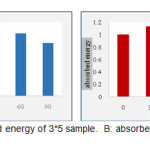 |
Figure 10: A: absorbed energy of 3*5 sample. B: absorbed energy of 3*6 sample Click here to View figure |
It is noted that, at the angle of 60 degrees, energy absorption increase slightly (2-4 percent) and decrease about 15 percent at 90 degrees and it changes as a function of steel material and span at 30 and 45 degrees. In 30 degrees with span increasing from 5 to 6 meters, the energy absorption increases from 7 to 13 percent but in 45 degree angle at 5 meters span, its increment is 13 percent and in 6 meters, the increment is 7 percent.
 |
|
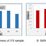
As it is noticeable from Figure 11, stiffness of reinforced shear wall with both sides and usual fibers is influenced by fiber orientation, span length and steel kind. Also the ductility diagram of reinforced steel shear wall is given in Figure 12.
 |
|
Calculation of Force Modification Factor: After averaging of reinforced and usual steel shear wall models, force modification factor is given in Table 2.
Table 2: The averaged Force Modification Factor of reinforced and usual steel shear wall
|
µ |
Ω |
Rµ |
R |
|
|
Ssw |
7.23 |
2.39 |
3.52 |
8.48 |
|
Cs |
3.90 |
2.74 |
2.35 |
6.6 |
Conclusions
In this paper, seismic behavior of steel shear wall reinforced with fiber polymers, under different angles, was investigated, and some models for estimate the seismic parameters were analyzed in nonlinear method and here are the results:
- It is noticed that, if there is no lateral displacement limit, capacity of reinforced shear wall will rise but steel shear walls behave in complete elasto-plastic way, which this behavior shows the preference of fibers in improve the seismic parameters and behavior of the system. Therefore the polymer cover will increase stiffness, shear capacity and energy absorption.
- However polymer fibers will cause increment in stiffness, shear capacity and energy abruption but the ductility of reinforced shear walls is always less than the unreinforced ones.
- The polymer cover has a little effect on resistance coefficient of reinforced steel shear wall. Samples stiffness would increase by the polymer cover but this increment is affected of span length, in other words, with increasing span its ascending rate would be higher.
- Span length increasing has no serious impact on strength coefficient and ductility of steel shear wall but increases ductility of reinforced shear wall 12 %. The most impact of span length increment is on energy absorption and shear capacity which increase them almost 50% and 30%.
- It is noted that, at the angle of 60 degrees, energy absorption increase slightly (2-4 percent) and decrease about 15 percent at 90 degrees and it changes as a function of steel material and span at 30 and 45 degrees. In 30 degrees with span increasing from 5 to 6 meters, the energy absorption increases from 7 to 13 percent but in 45 degrees angle at 5 meters span, its increment is 13 percent and in 6 meters, the increment is 7 percent
- Shear capacity ratio of reinforced shear wall with fibers in both sides is 10% more than fibers with different angles.
References
- Astaneh-Asl, A, Seismic Behavior and Design of Steel Shear Walls, Steel TIPS Report (2001)
- Takanashi, Y., Takemoto, T., and Tagaki, M., “Experimental Study on Thin Steel Shear Walls and Particular Bracing under Alternative Horizontal Load” Preliminary Report, IABSE, Symp. On Resistance and Ultimate Deformability of Tsructures Acted on by Well-defined Repeated Loads, Lisbon, Portugal (1973).
- Torii, S., Teramoto, T., Kihara, H. and Kitamura, H. The Response Control Design of High-rise Building With Low Yield Steel Wall. Proceedings on CD-Rom, 11th World Conference on Earth. Engrg., Acapulco, Mexico, Paper No. 97 (1996).
- Yamaguchi, T., et al.,. Seismic Control Devices Using Low-yield-point Steel. Nippon Steel Technical. Report. 77, 65-72. (1998).
- Elgaaly, M. and Caccese, V. “Post-buckling Behavior of Steel- Plate Shear Walls under Cyclic Loads”, J. of Str. Engrg. ASCE, 119(2), 588-605(1993).
- Rezai, M. Seismic Behaviour of Steel Plate Shear Walls by Shake Table Testing. PhD Dissertation, Department of Civil Engineering, University of British Columbia, Vancouver, Canada. (1999).
- Behbahanifard M, Grondin G, Elwi A. Experimental and Numerical study Investigation of Steel Plate Shear Wall, University of Alberta, Report No: 254. (2003).
- Timler, P. A. and Kulak, G.L., “Experimental Study of Steel Plate Shear Walls”, Structural Engineering Report No. 114, University of Alberta, Canada (1983).
- Driver RG, Kulak GL, Kennedy DJL, Elwi AE. Cyclic test of four-story steel plate shear wall. J Struct Eng-ASCE ;124(2):112_30 (1998).
- Sabouri-Ghomi, S., and Roberts, T.M. “Nonlinear Dynamic Analysis of Steel Plate Shear Walls Including Shear and Bending Deformations”, Engineering Structures, 14(5), 309-317 (1992).
- Hatami , F, rahaei,A, “Evaluation of Steel Shear Walls Behavior with Different Stiffeners of Middle Storey Beams"; 7th International Conference on Multi-purpose High-rise Towers and Tall Buildings (IFHS2005); Dubai, UAE; 10-12 December (2005).
- Jones, R. M., Mechanics of Composite Materials, 2nd Edition, U.S (1999).